|
|
|
|
|
the
Mountain Computer
Expansion Box
a legendary expansion to the Apple ][
series
reverse engineered and de-mystified |
|
Page
No.:H054-4 |
|
|
|
|
|
|
Copyright note: The
pictures used in this page, have been taken from members
gsmcten, macnoyd* and Keatah ( all members at the
Applefritter Forum
)
* the pictures from macnoyd, result from the ebay offer he
successfully won
Therefor the copyrights of the pictures displayed at this
page remain of course to the members at AF whom the units
belong.
The other pictures here resulting from the reengineering
process remain with their copyright to me and none of the
contents from this
page may be used ( not even partially ) in any other webpage
without the permission of the copyright owners.
|
|
|
|
|
|
|
|
|
|
|
|
| |
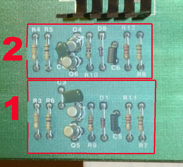
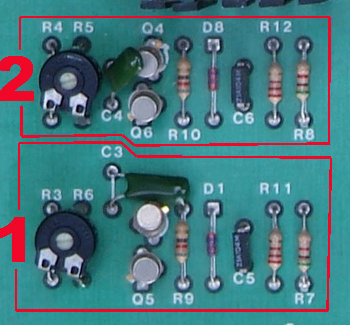
Well in this page i want to link the theory together with the "real
world" by displaying pictures of details from the mainboard in
conjunction
with the function groups explained in the previous page. I will use the
same notations and the same numberings to enable a comparing
view
of both parts besides eachother ( if printed and placed besides eachother
).
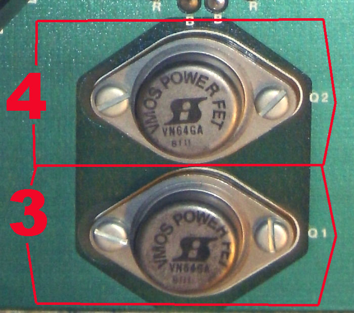
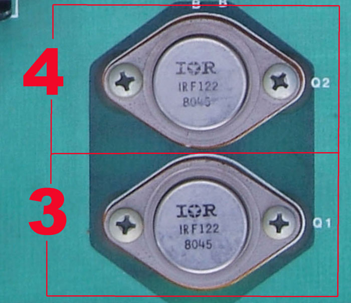
Within the thread at AF there has been mentioned, that there are in
general 2 versions of the box. The comparing of the differences
will be performed
also within this page.
| |
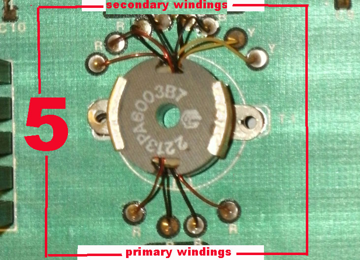
part 5 the "switching
coil" within the powersupply - it´s from plain view same
in both versions: |
|
| |
the
data from the switching coil
will be explained later in a own
page. That page contains the
data upon the material used for
the coil itself as well as - based
to measurements - the data to
the amount of windings.
The 2 primary windings at the
bottom of this picture are kind
of "centertapped" and the
opposing ends are tied to the
Power MOS FETs.
The secondary side at the top
of the picture consist of 4 in-
dependant windings that end
up at rectifying diodes and the
voltage get´s smoothened by
the added electrolytic capaci-
tors. Those voltages with
stronger current ( +5 Volt and
+12 Volt ) then are filtered with
coils that operate as "low pass"
blocking away the high frequen-
cy from the positive trace of the
circuitary.
|
 |
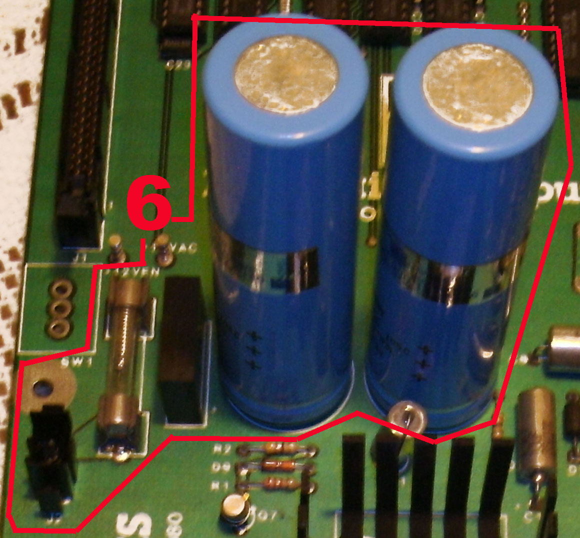
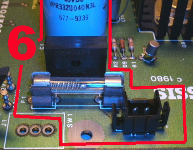
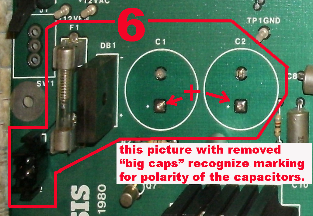
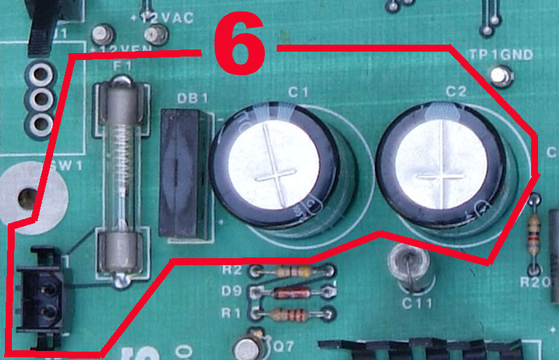
part 6 "the
primary rectifing part" within the powersupply
upfront of the regulating IC in part 7
- it´s from plain view same in both versions: |
| |
 |
|
The "big caps" may
be from different manufacturers - the
people at Mountain
Computer used capa-
citors from: Mallory
and other brands.
When replacing them
by repair the only
limitation will be to ensure that both
"big caps" should be from very same kind
and therefor they should allways be
replaced as pair - even also if only one
capacitor has been damaged.
When replacing of course the polarity
must
be correct - otherwise this
capacitors will |
|
 |
|
| |
 |
|
explode like bombs
! |
|
 |
|
|
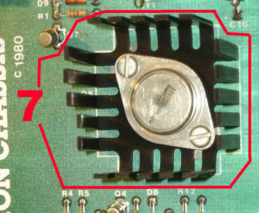
part 7 "the
first regulation of the voltage" within the
powersupply upfront of the "switching
powersupply"
- it´s from plain view same in both versions: |
The
SG340K 24 is a fixed
24 Volt
positive IC
Voltage regulator for regulation
of up to 1,5 Ampere.
If it must be replaced you
must be
sure that the replacement is able to
handle up to 50 Volt maximum
inputvoltage and it
must be
able to handle in normal operation at
least
1,5 Ampere !
|
 |
|
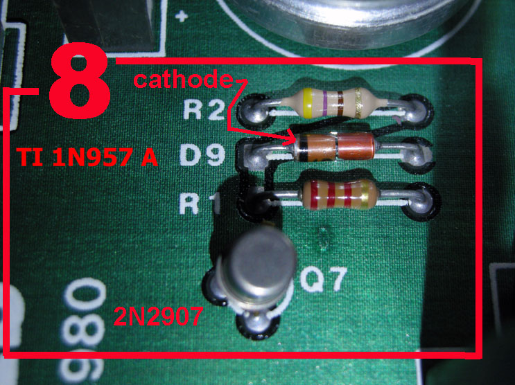
part 8 is the
"apple II power up detection" unit within the
powersupply
- it´s from plain view same in both versions: |
the "Apple II powered up detection"
makes
sure, that the Mountain Computer
Expansion
Box can only be used while the Apple II
is
powered up - this parts here detect, if
at the
Apple II the power is switched on by
detecting at the +12 Volt -
if power is present
- if not
this parts make sure that
the
oscilators ( part 1 and part 2 ) don´t
start
swinging and therefor then the
parts behind
the powersupply of the box ( behind the
"switching coil" remain without power.
|
 |
|
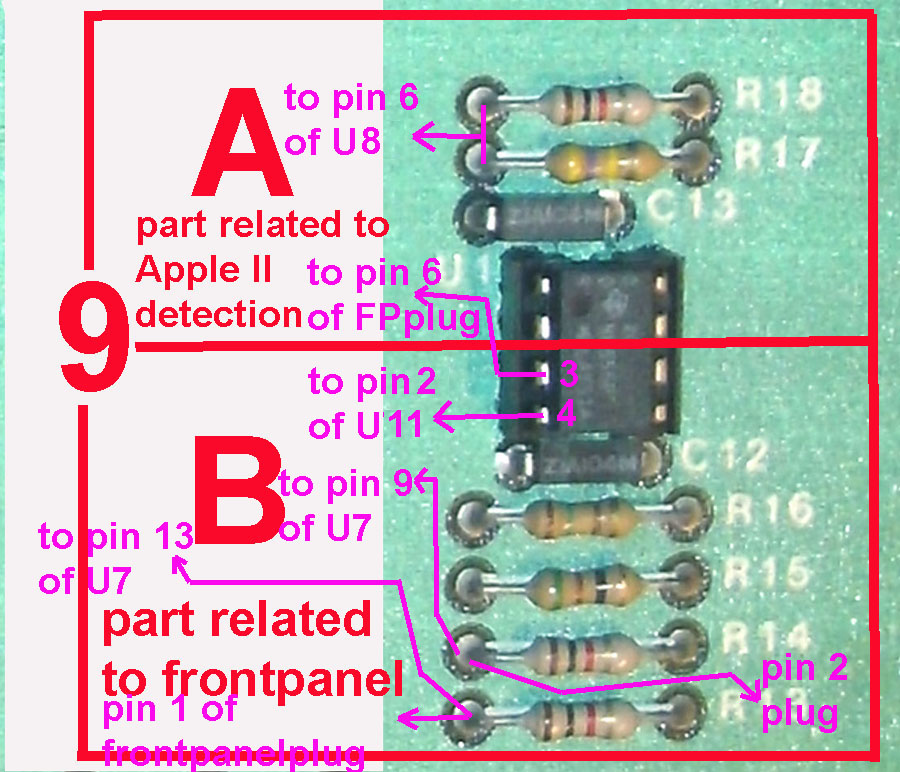
part 9 is
partialy the "apple II power up detection" unit
and the other part of the IC is responsible for
the frontpanel
- it´s from plain view same in both versions: |
| |
As explained in the picture right sided - the
common
connection of resistor R17 and R18 lead to pin 6 at U8.
Pin 3 of U1 ( the NE555 ) leads to pin 6 of the frontpanel-
plug and then within the yellow cable to the top of the
"in Use"-LED.
Pin 4 of U1 ( the NE555 ) leads up to pin 2 of U11.
The left side of the resistor R14 gets information from
pin 2 of the Frontpanel-plug and the red cable from the
center of the "select / deselect switch" and leads up to
pin 9 of U7.
And finally the left side of the resistor R13 gets info
from pin 1 of the frontpanelplug that has connection
by the brown cable to the "select / deselect switch"
and then leads up to the pin 13 of U7.
This four lines together mentioned in the previous page
as the "special-lines" or claimed at AF to be the "Riddle"
interact together with the line from the previous point of
part 8 ( detecting the +12 Volt from the Apple II as "power
up" signal ) as the complate Apple II detection circuit and
the functionblock that is responsible to determine if the
activity is to be performed by the Apple II or by the box -
depending to the status of the "select / deselect" switch !
The "trick" of selecting among the slots of the box and
the slots of the Apple II is executed by the selection of
"soft-switches" within the reserved adressing I/O range
of the Apple II. |
|
 |
|
| |
|
|
|
|
|
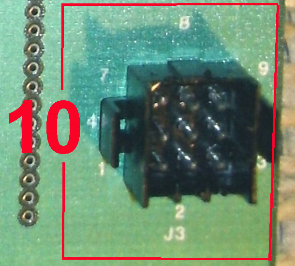
part 10 is
the connector to the frontpanel
- it´s from plain view same in both versions: |
|
|
 |
|
The left
picture displays the "front-
panel plug" connector in the very
right front of the mainboard.
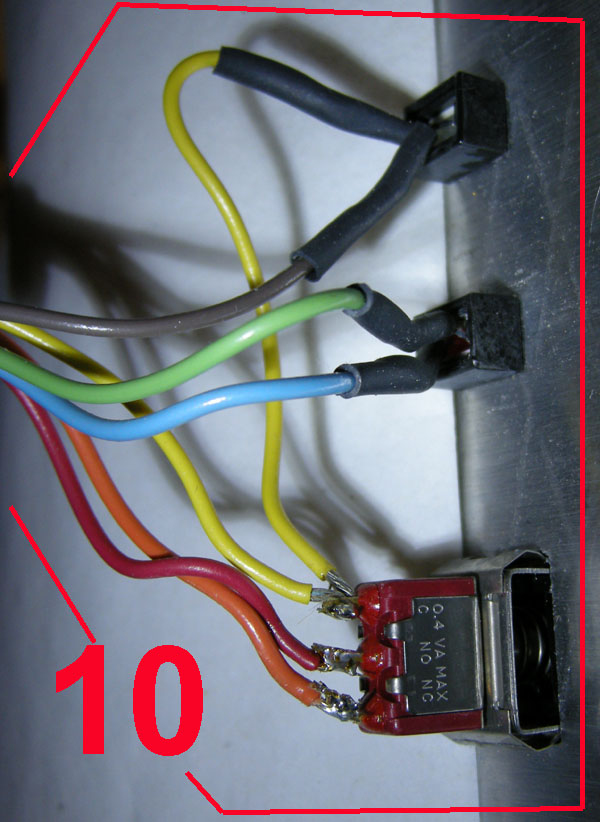
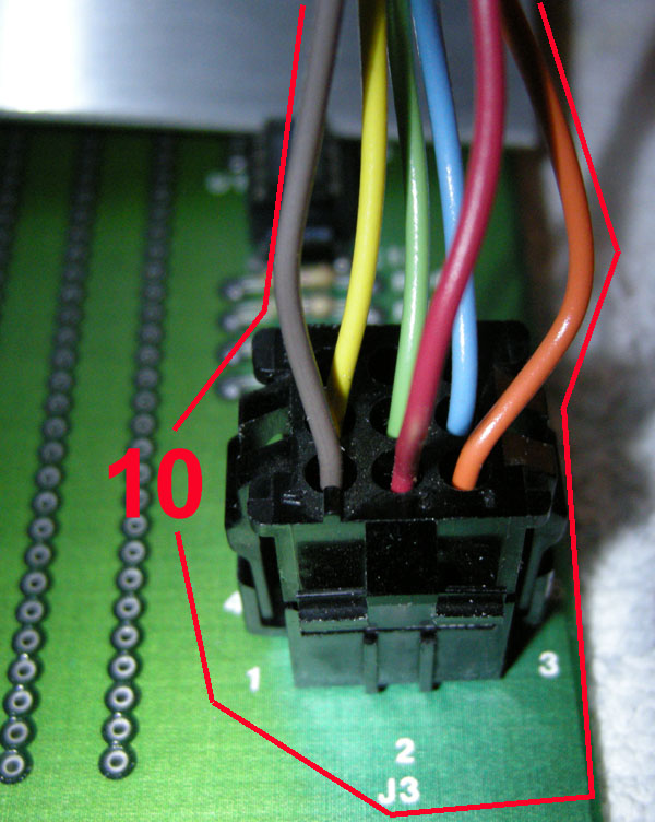
The picture at the left below displays
the plug from the wiring at the front-
panel inserted in that connector.
the upper right picture displays the
cables at the backside of the
frontpanel and the wiring.
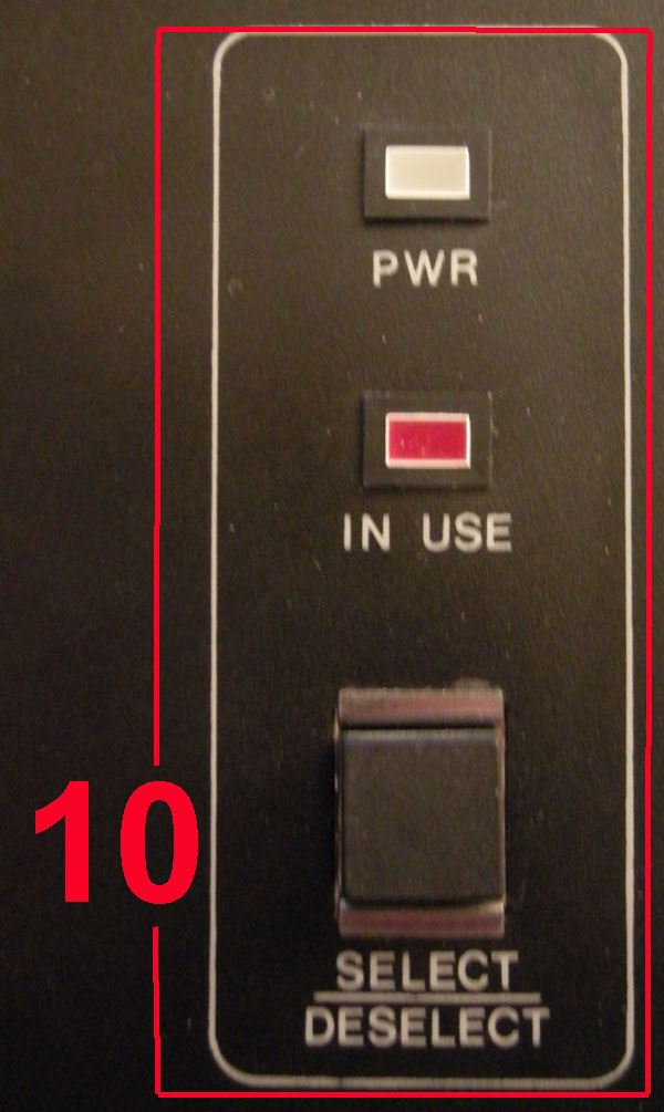
The picture at the lower right side
displays the frontview of the related
part of the frontpanel of the box -
with the 2 indication LED´s above the
"select / deselect" switch. |
|
 |
|
| |
 |
|
|
|
 |
|
|
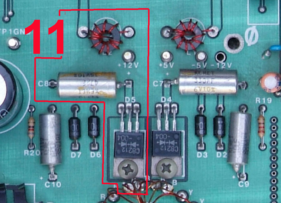
part 11 is
part of the powersupply behind the "switching
coil" and it´s responsible for the + 12 Volt
- it´s from plain view same in both versions: |
The 2 outer
pins of D5 ( C8212-004 ) are connected
to the
endings of one of the coils ( the 12 Volt one, consisting of
the thicker wire ) within the "switching coil" unit ( part 5 )
and then the rectified voltage is released at the centered
pin of D5 leading to the positive pin of the electrolytic
capacitor C8 that smoothens the voltage before it is
passed over to the Coil L2 which shall filter the high-
frequency noise away from the + 12 Volt branch and then
the voltage is delivered to the rest of the box ( in general
to the slots ) .
|
 |
|
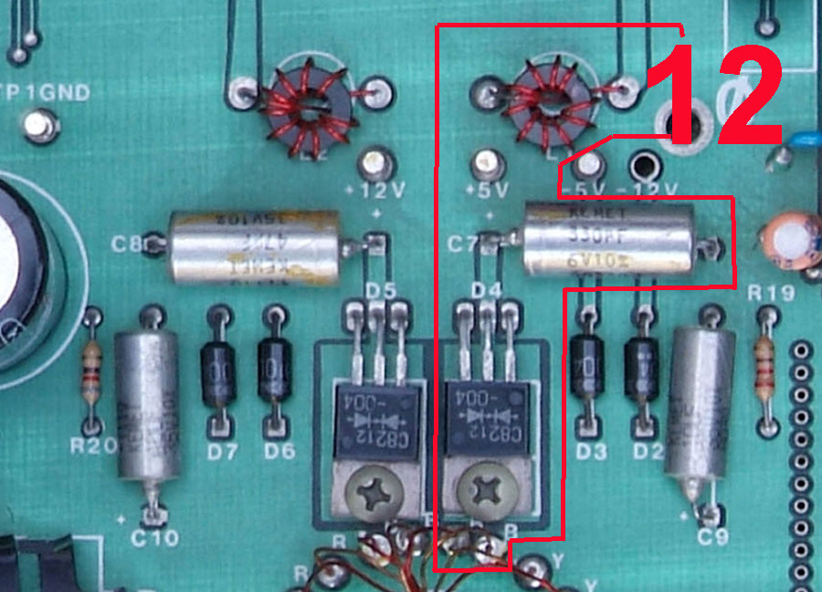
part 12 is
part of the powersupply behind the "switching
coil" and it´s responsible for the + 5 Volt
- it´s from plain view same in both versions: |
The 2 outer
pins of D4 ( C8212-004 ) are connected
to the
endings of one of the coils ( the 5 Volt one, consisting of
the thicker wire ) within the "switching coil" unit ( part 5 )
and then the rectified voltage is released at the centered
pin of D4 leading to the positive pin of the electrolytic
capacitor C7 that smoothens the voltage before it is
passed over to the Coil L2 which shall filter the high-
frequency noise away from the + 5 Volt branch and then
the voltage is delivered to the rest of the box ( in general
to the slots and to the IC´s U1 till U11) .
|
 |
|
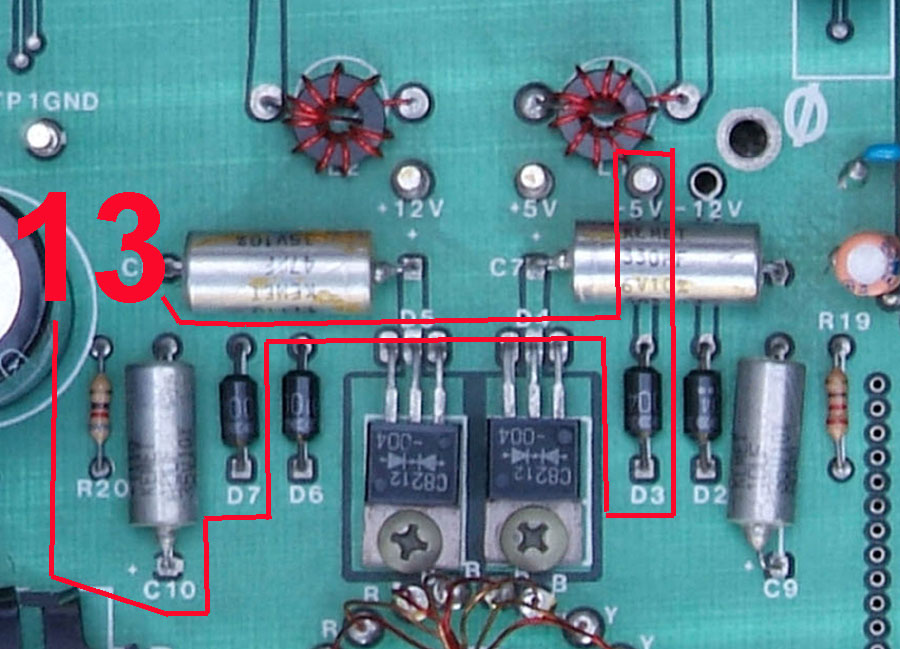
part 13 is
part of the powersupply behind the "switching
coil" and it´s responsible for the - 5 Volt
- it´s from plain view same in both versions: |
The 2
pins of D7 and D3 are connected to
the
endings of one of the coils ( the 5 Volt one, consisting of
the thiner wire ) within the "switching coil" unit ( part 5 )
and then the rectified voltage is released at the common
connected pins of D7 and D3 leading to the negative pin
of the electrolytic capacitor C10 that smoothens the
voltage before it is passed over to the resistor R20 which
shall filter the high-frequency noise away from the - 5 Volt
branch and then the voltage is delivered to the rest of the
box ( in generalto the slots ) .
|
 |
|
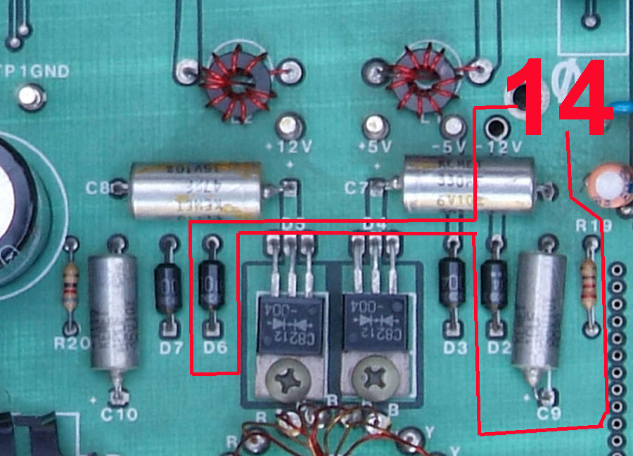
part 14 is
part of the powersupply behind the "switching
coil" and it´s responsible for the - 12 Volt
- it´s from plain view same in both versions: |
The 2
pins of D6 and D2 are connected to
the
endings of one of the coils ( the 12 Volt one, consisting of
the thiner wire ) within the "switching coil" unit ( part 5 )
and then the rectified voltage is released at the common
connected pins of D6 and D2 leading to the negative pin
of the electrolytic capacitor C9 that smoothens the
voltage before it is passed over to the resistor R19 which
shall filter the high-frequency noise away from the - 5 Volt
branch and then the voltage is delivered to the rest of the
box ( in generalto the slots ) .
|
 |
|
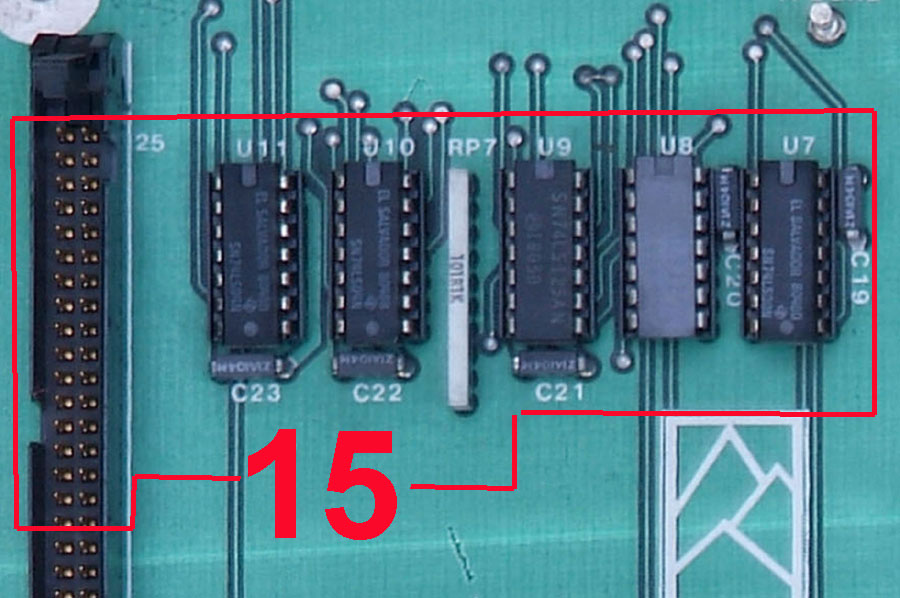
part 15 is
the part of the "control line function block"
within the "Apple part" of the box
- it´s from plain view same in both versions: |
the
control-line function block consists of
the IC´s
from U7 to U11.
U11 ( 74LS04 ) can be viewed as a kind of "amplifier" -
it only stregthens the signals that have been
"weakened" by the resistance ot the resistorpack at the
IFcard and the length of the 50 pin flatribboncable up to
powerfull signals again.
The same is valid to U10 ( also 74LS04 ).
The resistorpack RP7 operates as a network of "pullup-
resistors" that interact with signals at U11 and U10.
The IC´s U9 ( 74LS125 ) act like a
collection of 4
"pass through"-gates each also having own kind
of "enable"-pin that permits to lock or unlock a gate.
U8 ( 74LS02 ) and U7 ( 74LS08 ) perform
the "logic-
knitting" where some signals are linked together and
act like a kind of "logical-switches" that permit the use
of the box-slots or disables them. here is the logic of
the "soft switches" integrated together with the inter-
action with the "select / deselect" switch and the lines
that lead to the indication of the "status of the box"
at the frontpanel displaying if the the Apple II is "power
up" and the box is "selected" or not. |
 |
|
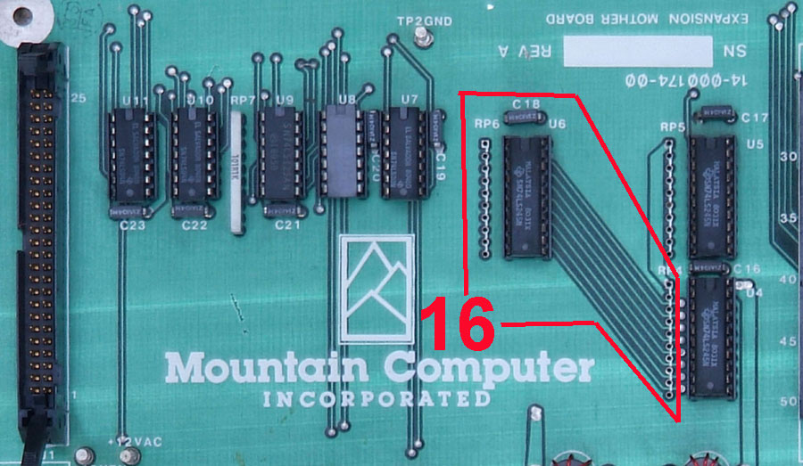
part 16 is
the part of the "data line function block"
within the "Apple part" of the box
- it´s from plain view same in both versions: |
U6 is a bus
transciever ( 74LS245 ) - it can be
compared
to a valve with 2 functions: one function permits the
water to flow or to be shut ( this is performed by the
pin 19 - CE = Chip Enable ) if that pin gets 5 Volt it
permits the flow of the data and if at pin 19 is 0 Volt
present the chip "shuts communication" and behave
to be "invisible" in both directions.
the second part of the control may be compared to
valves, that permit either the warm water or the cold
water to flow. At the IC this is performed by the pin 1
which is at the IC called DIR and that controls the
direction in which communication may flow
- it determins if the information is from slot of the box
to Apple II or from Apple II to the slots of the box.
The chip controls 8 lines ( D0 to D7 ) which represent
the entire databus. |
 |
|
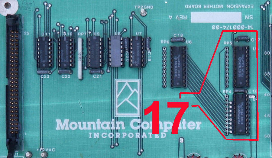
part 17 is
the part of the "adressing line function block"
within the "Apple part" of the box
- it´s from plain view same in both versions: |
U5 and U4
are bus transcievers ( 74LS245 ) - they
can be
compared to a valve with 2 functions: one function
permits the water to flow or to be shut ( this is performed
by the pin 19 - CE = Chip Enable ) if that pin gets 5 Volt it
permits the flow of the data and if at pin 19 is 0 Volt
present the chip "shuts communication" and behave
to be "invisible" in both directions.
The second part of the control may be compared to
valves, that permit either the warm water or the cold
water to flow. At the IC this is performed by the pin 1
which is at the IC called DIR and that controls the
direction in which communication may flow
- it determins if the information is from slot of the box
to Apple II or from Apple II to the slots of the box.
U5 and U4 control the entire adressing bus.
The chip U4 controls 8 lines ( A0 to A7 ) which represent
the lower half of the adressingbus.
The chip U5 controls 8 lines ( A8 to A15 ) which represent
the upper half of the adressingbus. |
 |
|
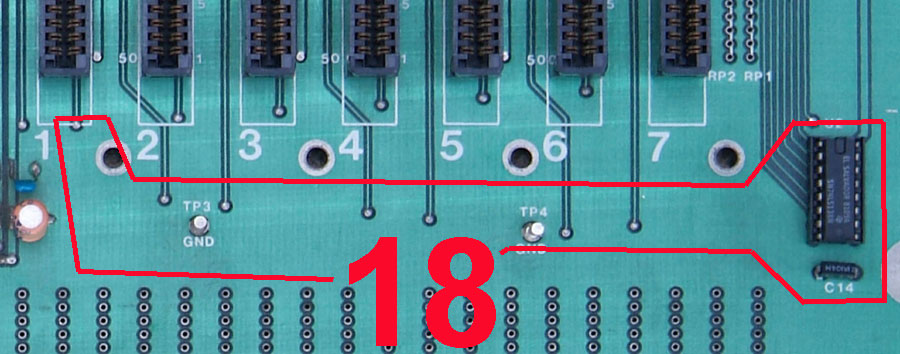
part 18 is
the part of the "device select function block"
within the "Apple part" of the box
- it´s from plain view same in both versions: |
The device
select function block operates by
delivering
the DEVSEL to one slot at
a time - that is performed by a
demuxer chip - in this case a 74LS138 that recives 3
adressinglines at the one input pin group and the other
group of input disables or enables the chip from decoding
the adressing lines if the correct settings are given. Then -
if decoding is enabled one of the 8 output lines of the
chips is set to low. This part is performed by the IC U3. |
 |
|
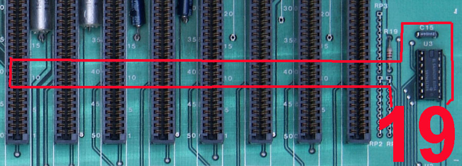
part 19 is
the part of the "I/O selection function block"
within the "Apple part" of the box
- it´s from plain view same in both versions: |
The device select function block
operates by delivering
the I/O SEL to one slot at
a time - that is performed by a
demuxer chip - in this case a 74LS138 that recives 3
adressinglines at the one input pin group and the other
group of input disables or enables the chip from
decoding the adressing lines if the correct settings are
given. Then - if decoding is enabled one of the 8 output
lines of thechips is set to low. This part is performed by
the IC U2. |
 |
|
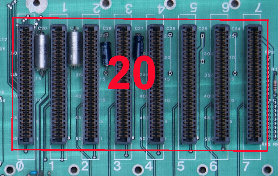
part 20 is
the part of the "Apple slots block" within the
"Apple part" of the box
- it´s from plain view same in both versions: |
The
block of the 8 Apple slots are
absolutely a copy of
the slots in the Apple II, with the exact same decoding
and absolut same signals as at the Apple II. The only
difference is given by the fact that by a switch of the box
the user may decide if the slot is enebled at the Apple II by
deselecting the box or disabled by selecting the box.
But none of the slots within the box is usable unless
the Apple II is connected correct and powered up.
The electrolytic capacitors located between
the slots just
buffer the voltages at the slots to avoid any kind of
dropout resulting from heavy loads. |
 |
|
|
|
| |
|
|
|
|
|
|
|
|
|
|
|
|
|
|
|
|
|
|
|
|
|
|
|
|
|
|
|
|
|
|
|
|
|
|
due to european laws
and german court decision:
I hereby declare no responsibility to any "deep links"
resulting from the links in this page. I have no influence
to the pages linked hereby in this page and the
contents in those pages. I therefor can´t take any kind of
responsibility to contents in the pages, where these links
direct the readers browser to nor to the
contents resulting from following up links from those
pages. The reference to contents by this links is dependent
ro the status of the date when the links have
been set ( April 2013 ) and it might occur that references
and contents may change by the fact that domains may have
been discontinued from their former owners.
In such cases i can´t take any kind of responsibility to
the changed contents. this is specialy valid to banners,
advertisements or merchandising links in the targeted
pages.
|
|