|
||||||||||||||
|
The story about
the Apple Seed Clone Cards of the Mountain Computer Music System |
||||||||||||||
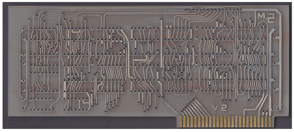
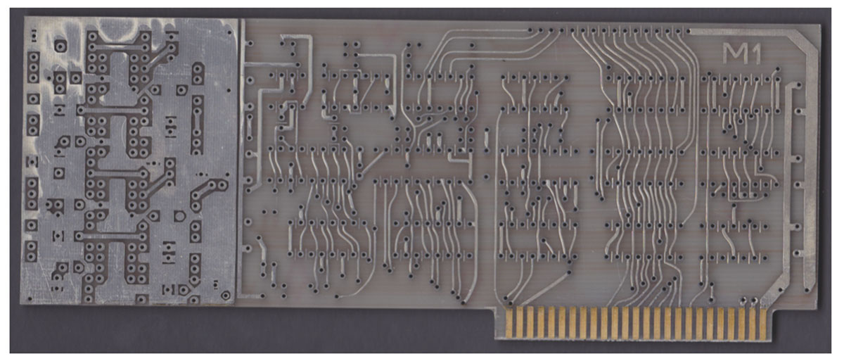
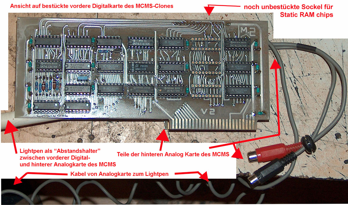
Several weeks ago i recieved an email from a friend with attached pictures of bare PCB´s. After short examination it turned out to be a set of 2 clone PCB´s of the Mountain Computer Music system manufactured by Apple Seed - a group of enthusiasts that reverse engineered in former days a lot of common interface cards and located in Ontario in Canada. They had even in that days a catalog of that clone cards with the listings of the components for assembly of that cards. I really got excited when i faced that pictures because the y permitted me to also view several traces that have formerly not been detected that well below of the circuit sockets and some of the components. Because my friend asked me for assistance by assembly of the cards i was glad to accept and offer him my time for the assembly. After the bare PCB´s arrived in my place i immediatly first scanned the PCB´s front and reaar side with high resolution for archieving purpose. Here are the scans: Digital Card Component side:
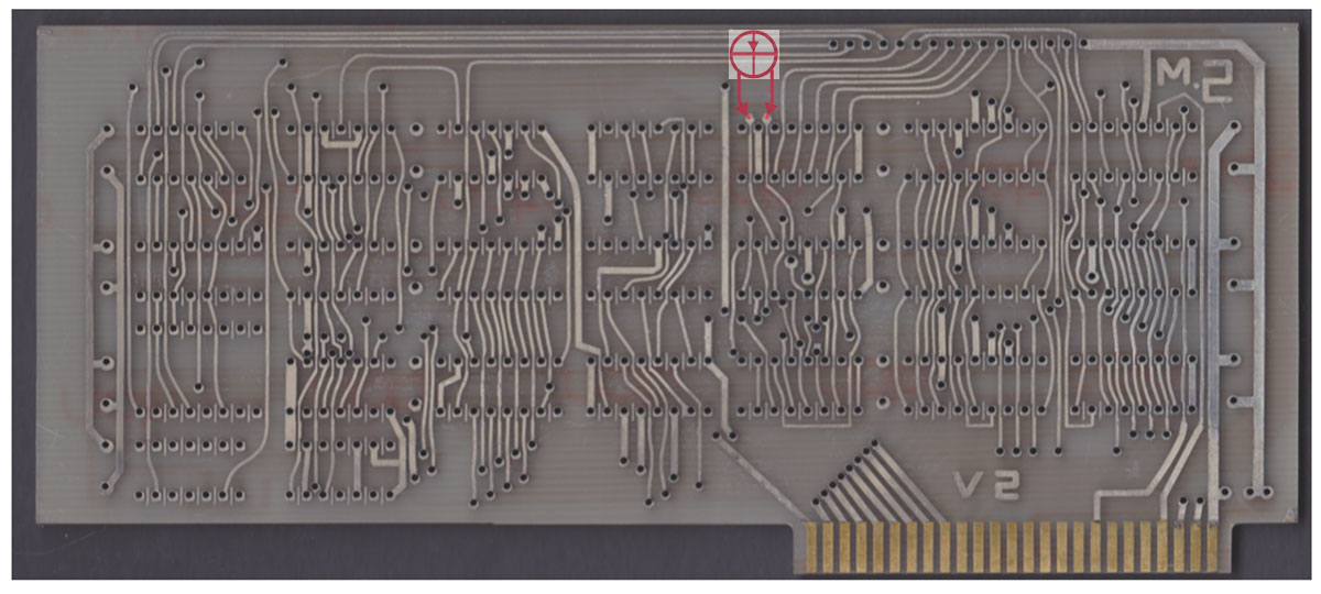
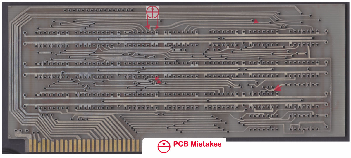
Digital Card Solderside:
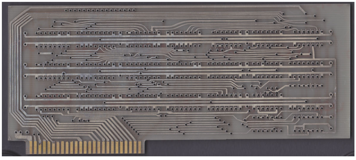
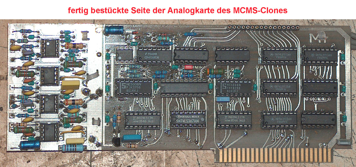
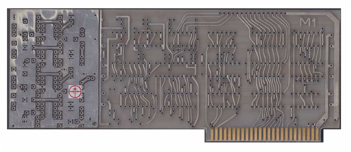
Analog Card Component side:
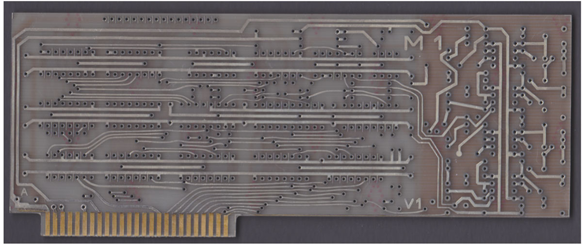
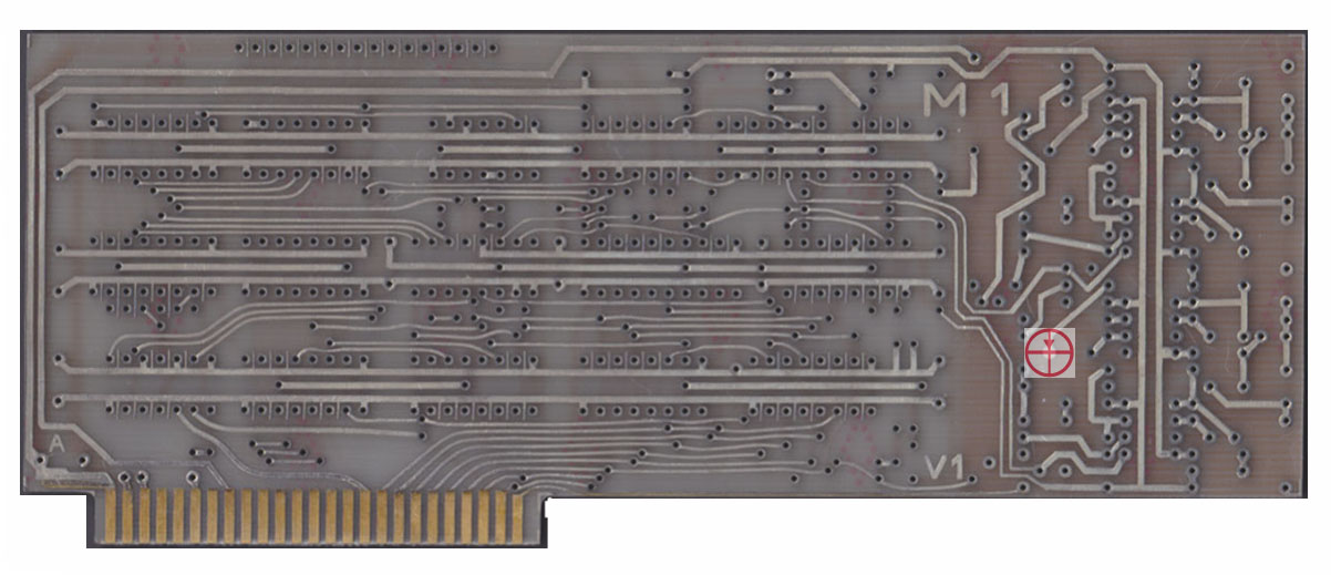
and the Analog Card soldering side:
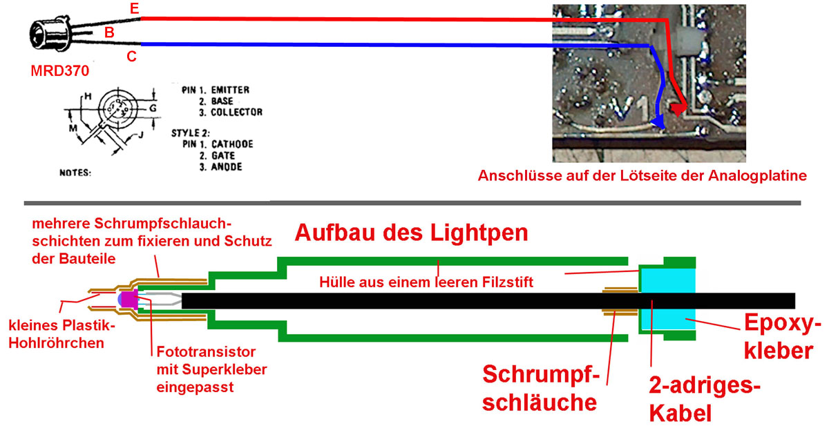
I used a empty case of a permanent marker,
soldered the phototransistor to the thin cable and covered the pins with
shrinking hose and then
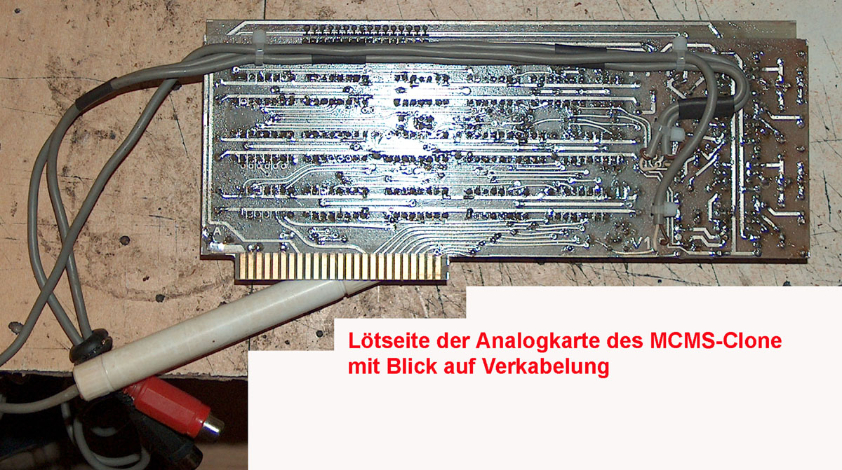
and next i assembled the analog card of the MCMS system:
Like i explained in previous pages the
connection used at the original cards of the MCMS system are of flexible
foil cable and though being
|
||||||||||||||
| Here is a view to the soldering side of the analog card after attaching and fixing the cables with cablebinder: | ||||||||||||||
 |
||||||||||||||
Important Hint: The Apple Seed PCB´s have some severe mistakes that you must bear in mind while performing the assembly: At the digital card two contact through holes are missing and that traces from topside must be contacted with the traces at the solder side by drilling and soldering at both sides see marks below. And at some points the holes are rather dangerous to neighbor contacts. That spots also have been marked.
And also at the Analog board there is
a drilling hole missing and must be added and the component must be
soldered at both sides
|
||||||||||||||
|
||||||||||||||
|
due to european laws
and german court decision: I hereby declare no responsibility to any "deep links" resulting from the links in this page. I have no influence to the pages linked hereby in this page and the contents in those pages. I therefor can´t take any kind of responsibility to contents in the pages, where these links direct the readers browser to nor to the contents resulting from following up links from those pages. The reference to contents by this links is dependent ro the status of the date when the links have been set ( April 2013 ) and it might occur that references and contents may change by the fact that domains may have been discontinued from their former owners. In such cases i can´t take any kind of responsibility to the changed contents. this is specialy valid to banners, advertisements or merchandising links in the targeted pages.
|