This pages were created as a reaction of the fact that within the
Applefritter-site a lot of threads are related to the topic of
the Apple-Disk II-
system. Due to the age of these diskdrives in a lot of cases they have
malfunctions... sometimes just by dirt, sometimes caused by
wrong
storage and sometimes just as the result of earlier bad treatment like
shocks or similar incidents.
So this pages will cover the entire topics of how this drives work, which
parts might become damaged and how to mantain this drives
by cleaning and adjustment. I will display pictures in detail with
markings inserted and comments to explain steps of service to
get that
drives running again in perfect shape. The order is related to the "toplist"
of malfunctions ( i.e. i will treat the topics in the order
sorted
how often the mistakes happen .... the most common first and the rather
rare mistakes thereafter ).
In the preliminary part i will first explain the way this drives work to
provide the user with some basic
knowledge..... this should be read too
because if you know how the drive works - you will know why you are doing
something and what the purpose of the task targets
for....
this will permit you to perform this tasks better by understanding the
task itself.
I hope this pages will become some kind of reference to the topic and
save in future a lot of redundant threads and help to keep this
drives
in good working condition.....
|
In the ancient days when this drives have been designed by Steve Wozniak,
the specialized chips for diskette-drives were horrible
expensive or not even designed ... so the Disk II -drive is equipped with
very simple logic chips from so called "standard series" ( i.e.
no specialized chips where used ).
But before we examine the Drive and its components we first should take a
closer view to the diskette ( media ) itself - this is important
for understanding later explenations. So lets start with the following
shematic-picture and the explanations of the picture in the text
below:
|
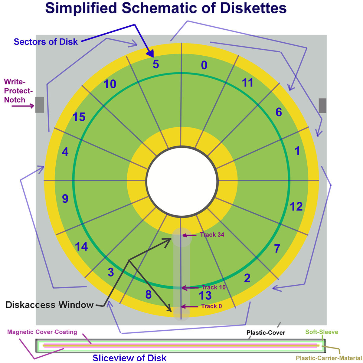 |
After the first overview lets
examine first the so called "Sliceview of Disk" at the bottom:
the basical center of a diskmedia is a circle of
plastic-carrier-material
that is covered with magnetic cover coating ( one side at Disks marked
with "1S" and if both sides are covered with the material its
marked as "2S" .... - allthough
this is in very many cases not true.... a lot of diskettes marked as "1S"
are in fact coated at both sides, but for some reason ( mistakes
in the surface - or just
because it was to much work to change the manufacturing-line ) they were
marked with "1S". So it was a common habit in old days to
tryout, if the backside
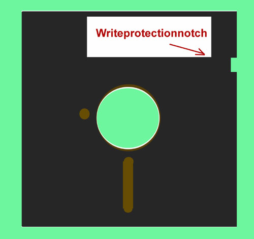
does work or not - and it therefor was also a common habit to punch a
read/write-notch in the cover with a so called
"Disknotchpuncher".
|
Disk with the common one notch for writeprotection |
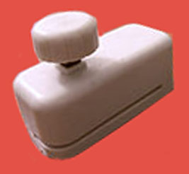
Disknotchpuncher
|
Disk after use of the Disknotchpuncher |
 |
 |
 |
That thin covered sheet of
plastic covered with a magnetic surface ( mostly on both sides )
is also marked to be "SD" ( for single Density = less quality of
magnetic-coating ) or as "DD" ( for Double Density = better
quality of magnetic coating ) .... there is also material sold
with marking "HD" used for Disks
with so called "High-Density" material - but this material can't be
used with any Apple Computer. It's "packed" in a soft sleeve to
avoid any kind of damage to
the surface. That "soft-sleeve" is within a cover made from thicker
resistant flexible plastic which is the cover you handle with
your hand.... - BUT:
Be CAREFULL ! In this cover is kind of
"window" which permits direct view to the basic-disk-material
itself - this is the window where the Read/Write-Head
slides along the material and reads the data - similar to the tape
- passing the readinghead in the recorder !
Never touch the surface of the Diskette
itself !!!
This can cause the diskette to become damaged severly and it gives
risk that dirt gets moved to the Read/Write-Head of the Drive
which is very extrem
sensible ! Back to the marking: 1SDD is for example single-sided
double-density.
------------------------------------------------------------------------------------------------------------------------------------------------------------------------------------------------------------------------------------
Now lets take a look at the upper part of the picture: before
starting any discussion about spinning and orientation lets
agree to the following facts...
this picture is a view from the top of the Disk towards the bottom
of the drive ! So if you take a look to the diskturntable and
the drivebelt from botton to the
direction of the top of the drive the motor and the disk is
spinning clockwise ..... but - if you turn the drive around and
take a look at the disk from the top of
the drive of course the turningdirection turn to opposite (!) so
the disk turns in fact counterclockwise (!). So now you will
understand that the orientation of
the sectors of the disk are numbered correct ! Spinning the disk
around counterclockwise if the sector 0 passes the Diskaccess
Window the third sector to
become visible will be the sector with the number 1 and then after
another 2 sectors again the third sector will be the sector with
the number 2 and so on.....
This skipping of sectors in the order on the physical disk is
called "interleave". At the beginning it may sound crazy... but
this is really the fastest way to read
or write a disk ! To understand this we will examine very basically
the things that happen after a sector has been read or written:
After the Bytes have been read to the disk-controller and moved by
the cable to the computer and there moved to the memory and the
computer gave the
instruction to fetch the next sector ( and bear in mind that this
tasks require some time ! ) in the meantime the disk of course
has moved a bit ahead ( 2
sectors ) so at the beginning of the third sector the
reading-access starts just right again..... - just imagine the
interleave would not have been executed ...
in thet case the read/write-head would be above the sector with the
number 3 and it would need a delay of another 13 sectors till
the sector with the number 2
would be availiable again at the Diskaccess Window !
In the very beginning of the
Apple the diskettes were formatted with only 13 sectors - but
after very few years it turned out to be better to use a format
of 16
sectors. It is very important to recognize this fact ! The timing
of the interleave is only determined by a time-delay-loop that
is given by the software of the
proms ( P5 and P6 ) in the disk-controller ! So now at this moment
just the facts: the numbers of the Proms of the 13-sector
version of the controller show up
with : ROM P5 is labeled 341-0009 and the ROM P6 is
labeled with 341-0010. The Controller with the 16 sector version
contains the proms P5A labeled as
341-0027-A, P5A 1981 while the P6A is labeled as 342-0028-A,
P6A 1981.
This is an important thing to recognize - because it is impossible
to read or write 16 sector format with 13 sector proms as well
as it is impossible to read or
write 13 sectors with a set of proms determined for 16 sector
format ! The timing delay loops within the software just won't
match with the speed and
therefor won't match with the interleave-timing - no way !
Allthough in the picture above both - the yellow and the light
green area is covered with the magnetic-coating... but only the
green area is really used within
the Disk II. With the 40-track drives a larger part of the inner
yellow area is additionaly used too....
Important at the moment is just the fact that track zero is at the
outer side and the tracks with the higher numbers are orientated
towards the inner circle.
In another later part we
will switch back to this picture for more detailed view and
explanation .... but at the moment we can stay with the now
explained
knowledge.....
Now after the view to the diskette we can take a closer view to the
details of the drive. The schematic in the picture below shows
first of all a kind of
explosionview splitted to function groups that have been taken
apart to color groups. Colors similar to eachother belong
together. In the text below of the
drawing - the groups will be explained from the top of the drawing
down to lower levels towards the bottom of the drawing
....... after the explenations
this groups will be also documented with pictures that contain
additional comments in the pictures ....
|
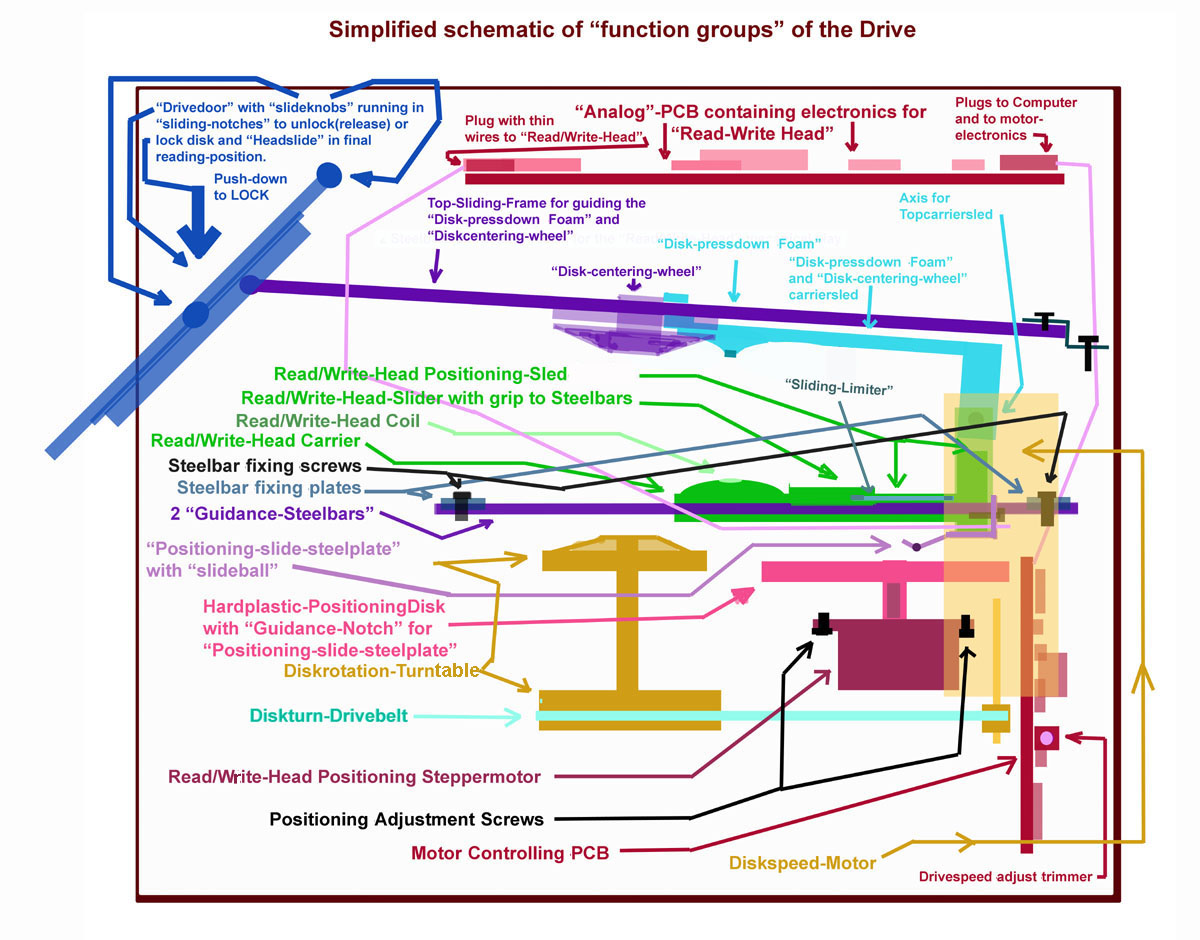 |
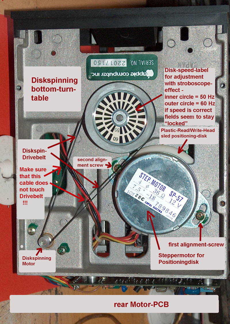
When you have removed the cover of
the DISK II - drive by untightening the 4 screws at the bottom
and sliding off the hood, you will first get the sight of the
so called "Analogboard". At the front left side there is a plug
with very thin wires - be very carefull with that wires - it's
the bunch of wires to the read/write-
head of the drive and they may not be damaged ! At the center of the
rearpart a very thick connector in the middle consists of a
bunch of cables that lead to
a PCB at the rearpart of the drive - which control the motor for spinning
the disk and the electronics to drive the stepper motor which is
responsible for the
positioning of the "read/write-head sled". The "read/write-head-sled" is
not visible at the moment because its beneath the shielding-top
- it consists of 2 parts:
the top part the moves upward and downward by opening/closing the drive
door and the Steelframe where the sliding-mechanic runs along.
That steelframe
carries in the frontmiddle the mechanic for centering the disk in the
proper position when shutting the drive door, the upper part of
the sled with plasticpart
that i call the "Disk-pressdown-Foam" - if the door gets shut in front
with a disk inserted it gives light pressure to the disk to make
sure that it is fixed close to
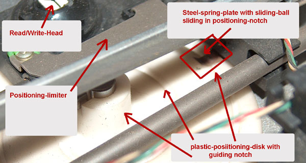
the "read/write-head at the bottom part of the lower part of the sled. At
the one side of the sled there is a piece of steel mouted that i
call the "Sliding-limiter" -
this part makes sure that the "read/write-head" does not move out of its
disired bounderies. We will later take a closer examination to
this part of steel when
treating the task of positioning-mantainance.......
The analogboard is fixed at the rearside by running along within notches
of the plastik frame and at the front its fixed at both sides
with a scew.
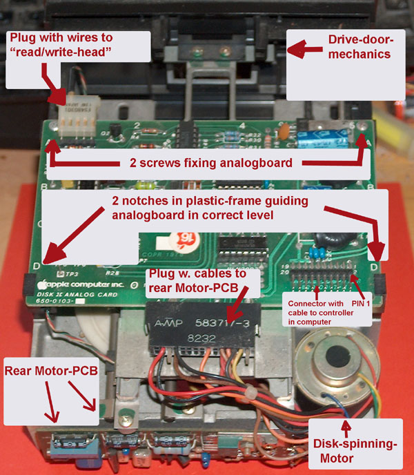
So now at the moment first of all some pictures in the order what you
will see while dismounting the drive:
| View to the top of the
drive with analogboard in place |
 |
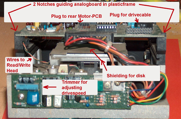
| View to the rear of
the drive with the analogboard in place |
 |
|
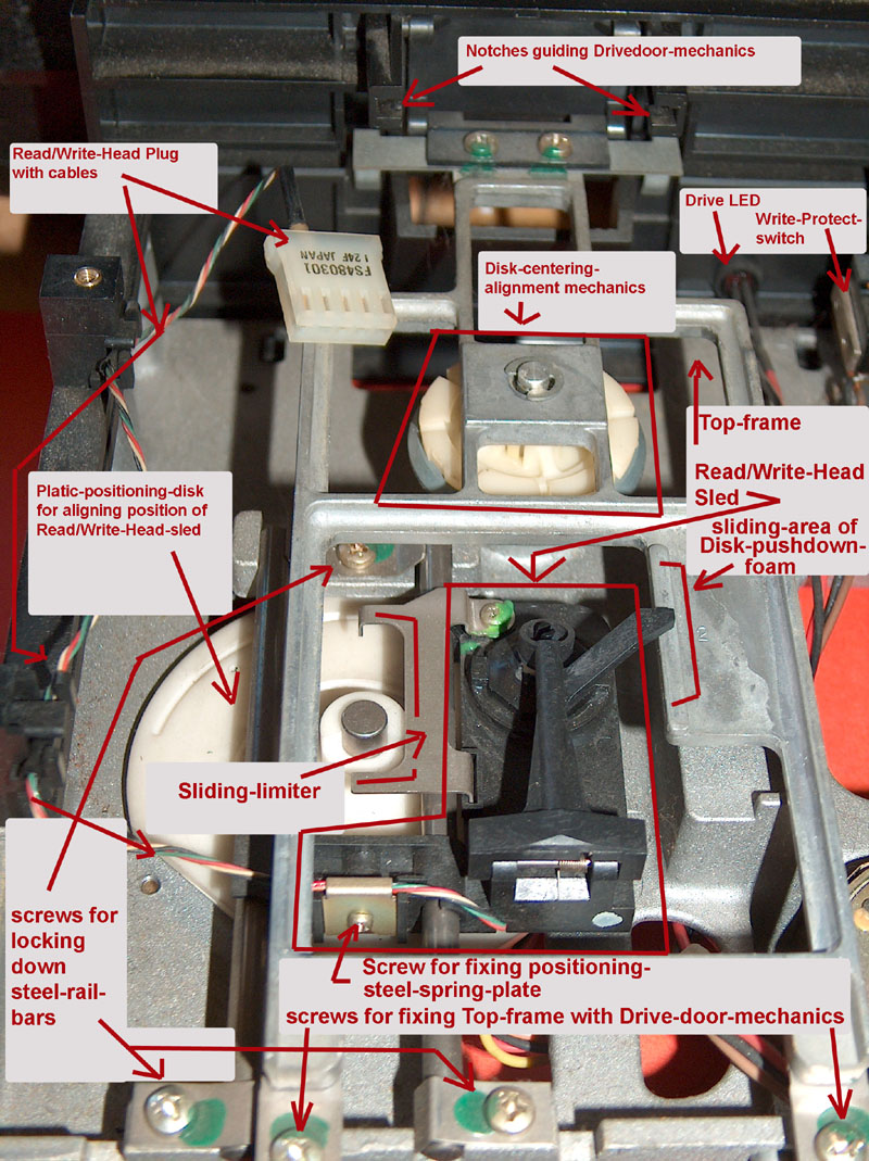
|
| View to the Drive
after unmounting the analog-board |
 |
|
So now after this pictures lets
take a short look from the bottom of the drive to get some more
orientation on the components:
| commented bottomview
of the drive: |
 |
|
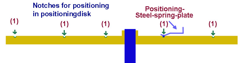
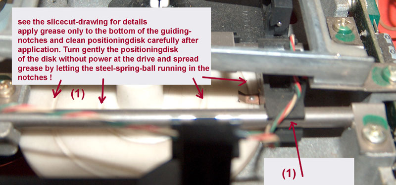
and to get the view
of the positioning-mechanic complete
here another detailed view of the steel-sliding
mechaninc
at the plastic-positioning-disk with close view
to the
steel-sliding-plate with the sliding-ball : |
 |
So now some
additional remarks:
Up to this point the DISK II has been shown
that far that we can treat first the
typical mantainance tasks that could be
performed also at drives that are
working but are for example just noisy or have
minor problems resulting from
dirt or similar problems.
In the next part of the text and pictures i
will therefor explain this servicetasks
and i will treat the problems related with
calibration of speed and track zero
in the following additional pages to keep the
pages handy for fast loading -
at the end of this page there will be the links
to the page about calibrate speed
and a page about calibrating track zero.
Nevertheless i advice to also read the
following text and view the pictures too,
because after a repair it is recommended to
carry out the task of supplying
oil/grease to moving parts and cleaning the
read/write head to ensure proper
operation of the disk also in the future.
|
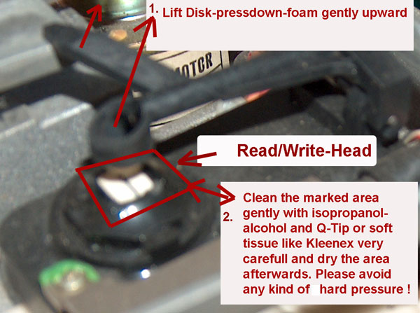
Cleaning the Read/Write-Head
|
 |
|
|
Getting the oil or grease to the right places and making sure
that it keeps there and only there !
first again a short explenation:
If you use oil ( specially if the oil is very liquid-fluent )
like the oil used in sewing machines isn't a very good idea.
First of all in the following time you
can't predict which directions the oil will start running to
after the drive was closed, where some drops might fall down (
i.e. onto the inserted disk ? )
and some kinds of oil have the bad habit, that they get thicker
like resine or vaseline and then they don't provide good sliding
attitude anymore.
The best experiences i have made with little more expensive
synthetic-grease as it is used for ballgears or
positioning-chains in robotic systems.
The consistency is quite similar to warm margerine, but it
doesn't drop around, but just is adhesive to the spots where it
has been applied to.
Such grease remains for years in the applied area and does not
change its attitude to keep a very slippy and smoth sliding
between the moving parts.
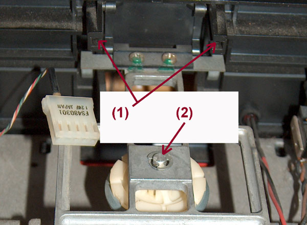
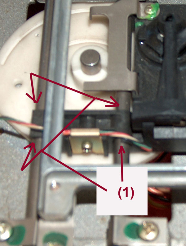
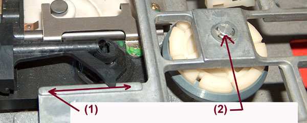
In the pictures below i will mark areas with
(1) or
(2). The marking with
(1) will mean that grease
should be applied ( only very few ) and the marking
(2)
will indicate where a very thin fluid oil should be applied.
|
|
|
download this page as
PDF-file

continue to next page about
speedadjustment of the drive
continue to the page about
calibrating the track zero
continue to the page about
advanced adjustment of the offset
of the electronical Read/Write-Head compensation cycle
common mistakes at the Disk ][ drive and the controller
making a homebrew replacement of the DuoDisk Cable |
|
|