Home
Commonly Failing Electronic Components
(in old computers)


Tantalum Capacitor

Capacitors that use a tantalum based dialectric. Used mainly to filter small voltage rails.

These are a common failure in IBM 51xx computers and related IBM cards (e.g. IBM EGA card).

These either go open or short. If they go short, the power supply in the IBM 51xx computer becomes overloaded and will normally not work (although the fan may still turn).

My observation is that these tend to fail on application of power, or shortly after (say, within 30 seconds) and that the likelihood of failure is greater if the capacitor has been unpowered for many years.

These capacitors sometimes fail quite dramatically, from a shower of spark-like particles to literally exploding, or both. Three examples are shown below. The first example produced a shower and the only evidence of damage to the capacitor is a small black eye/hole. I have seen that a few times. The second example is that of an exploded tantalum (that particular example emitted a fragment that burnt my carpet).


Do not assume that because a tantalum capacitor shows no damage, that it is good. Faulty tantalum capacitors often show no visible indication of failure.

Tantalums have polarity. They need to be inserted the right way - positive leg into positive hole, and negative leg into negative hole.

On the IBM 51xx motherboards and cards, IBM have used a common value of 10µF/16V. They typically have "106 16V" or "10µF 16V" marked on them.
They either have two or three legs. Two-legged 10µF/16V replacements can be found easily.
Click here for information about the three-legged tantalums on the IBM 51xx motherboards/cards.

Note that the early IBM 51xx motherboards/cards have three-hole positions containing a two-legged tantalum. Such three-hole positions are not designed for three-legged tantalums. Click here to see an example.


Dynamic RAM Chips

Typical practice in the 1980s was to mount RAM chips in sockets, because of the relatively high failure rate.

IBM 5150

In the IBM 5150 (PC), a failure of any chip in the first bank of RAM (bank 0), results in what appears to be a 'dead' motherboard. That is not easy to diagnose because in the 5150, the first bank of RAM is soldered in. One way to diagnose this particular problem is to use a suitable SuperSoft/Landmark diagnostic ROM in socket U33 (replacing the existing BIOS ROM).

IBM 5160

In the 5160 (XT), a failure of any chip in the first bank of RAM (bank 0) also results in what appears to be a 'dead' motherboard. In the 5160 though, all RAM chips are in sockets and so one can swap the banks about to diagnose such a failure (assumption: the bank of RAM being swapped into bank 0 is good). Note that for the 640KB version of the 5160 motherboard, you can only swap bank 0 with bank 1, because banks 0 and 1 comprise of 256Kbit chips and banks 2 and 3 comprise of 64Kbit chips.

IBM 5170

In the IBM 5170 (AT), a similar thing happens - a failure of any chip in the first bank of RAM (bank 0) results in what appears to be a 'dead' motherboard.

For a type 1 motherboard, which has 36 RAM chips making up 2 banks of RAM, the failure can be diagnosed by swapping the 2 banks of RAM (bank 1 chips into bank 0). That will only work if all RAM chips in the second bank are good. If the motherboard was recently working, then the probability of that is high. If you've recently acquired the motherboard (in a faulty state) then any number of RAM chips can be faulty, including those in the second bank.

Also, the use of a POST card (set to port 80H) will identify a RAM chip failure in bank 0. Look for a repeating pattern of three byes that starts with DD. The second byte is for bits 8 to 15 and the third byte is for bits 0 to 7. For example, DD/80/00 indicates that bit 15 in bank 0 has failed.
DD/00/01=0, DD/00/02=1, DD/00/04=2, DD/00/08=3, DD/00/10=4, DD/00/20=5, DD/00/40=6, DD/00/80=7
DD/01/00=8, DD/02/00=9, DD/04/00=10, DD/08/00=11, DD/10/00=12, DD/20/00=13, DD/40/00=14, DD/80/00=15
If you only see DD/00, that means that one of the two parity chips is faulty.

Type 2 and type 3 motherboards have 18 RAM chips making up 1 bank of RAM. If the motherboard was recently working, and the problem is RAM chip failure, then the probability is high that only one RAM chip has failed, in which case, swap out the 18 chips one at a time with a known good chip. If you've recently acquired the motherboard (in a faulty state) then any number of RAM chips can be faulty, which means that to identify RAM chip failure, you might need to replace the entire bank with 18 known good chips.
Also, the use of a POST card (set to port 80H) will identify a RAM chip failure in bank 0.


Line Suppression Capacitor

Another common failure in old computers is that of the line suppression capacitor.
'Line Suppression' refers to the functionality that the capacitor provides, not to the capacitor's dialectric.
May also be referred to as 'suppression capacitor', 'EMI suppression capacitor', 'line filter capacitor', 'mains filter capacitor'.

These capacitors are in the power supply. They absorb radio frequency interference (RFI) in/out of the AC power (line) connector, and absorb incoming power surges/transients. Because they have to tolerate surges/transients of varying degree over a long period of time, they are specially designed to take that kind of punishment (without catching fire, etc.)

There are two classes of line suppression capacitor, X and Y, and those can be divided further into sub-classes, e.g. X1, X2, Y1
More information on classes is in the 'futher reading' links below.

Aged line suppression capacitors tend to rupture. An example of an old RIFA made capacitor is pictured below.

For RIFA made capacitors like this one, the rupture is accompanied by smoke and a strong foul odour.
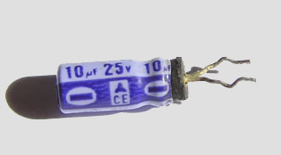
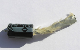
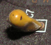
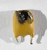
The odour will persist until the capacitor is removed. The capacitor contains fluid, which may leak out.
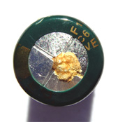
Do not touch the fluid (it may be carcinogenic, or otherwise toxic).

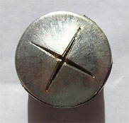
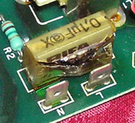
The "X" in "0,1µF@X" indicates that this capacitor is of class X  (expected because it sits between line and neutral).

When sourcing a replacement for a faulty item, note that you need to match three things:
1. Capacitance (e.g. 0.1 µF);
2. Maximum working voltage (e.g. 275 volts AC) (can use something rated higher);
3. Class (i.e. replace X with X, replace Y with Y).

Further reading: 'Line-Filter Capacitors' section of my.execpc.com
Further reading: EvoxRifa document: Capacitors for RFI Suppression of the AC Line   (1996) (includes safety standards)
Further reading: EPCOS - EMI suppression capacitors   (2009) (includes safety standards)
Further reading: 'Noise suppression capacitors on AC mains' section of www.capakor.com


Aluminium Electrolytic

Note: Aluminium is also known as aluminum (no second 'i').

Aluminium electrolytic capacitors (big and small) in power supplies and in monitors. Over years, the electrolyte within slowly dries out. The capacitance goes out of tolerance and/or the ESR (equivalent series resistance) increases.

Sometimes poor engineering causes failure well before expected. For example, failure of C11/C13/C14 in the power supply of the IBM EGA (5154) monitor was common (due to overheating).

The vast majority of failed aluminium electrolytic capacitors that I have found have no visible indication of failure/deteriation. Some examples follow of units that I have found where there is a visible indication. The second example whistled as it failed. I consider the fourth example to be very rare.


If you are testing aluminium electrolytics using a capacitance meter, note these two things:
1. Aluminium electrolytics typically have a tolerance in capacitance of +/- 20%;
2. You may measure the capacitance within tolerance, but the capacitor is faulty because its ESR has increased beyond the point where it can be tolerated within the particular circuit it is fitted in.

When sourcing a replacement for a faulty item, note that you need to match four things:
1. Capacitance (e.g. 100 µF);
2. Maximum working voltage (e.g. 50 volts);
3. Temperature (e.g. 85 degrees Celsius).
4. ESR - replace a low ESR capacitor with another low ESR one.

You can substitute a larger working voltage capacitor. For example, if a failed capacitor is rated at 16 working volts, you can substitute a 25 volt one.

Some aluminium electrolytics are designated as 'low ESR'. As the words suggest, the capacitors are made to have a low ESR (as compared to 'normal' aluminium electrolytics). Seen a lot in switchmode power supplies. My understanding is that there is no industry standard and accordingly, that makers themselves decide on what is 'low ESR'. The words 'low ESR' may (repeat: may) appear on the capacitor. Some makers simply use different coloured lettering on their capacitors to signify 'low ESR'. For technical reading on the 'low ESR' subject, see http://www.illinoiscapacitor.com/pdf/Papers/low_ESR_fact_or_fiction.pdf

85 degree capacitors are common in vintage computer equipment. Some capacitors in vintage switch mode power supplies are rated at 105 degrees. Some capacitors in vintage switch mode power supplies are rated at 85 degrees, but should have been made 105 degrees.

Aluminium electrolytic capacitors used in computers have polarity. They need to be inserted the right way (positive leg into positive hole, negative leg into negative hole). Markings on the capacitor will indicate polarity, and on new aluminium electrolytic capacitors, the shorter leg is the negative one.