Tape data processing
( all MZs )
|
| General |
|
This page originally was written for the MZ-700. But the principles
of the tape data structure are identical for all MZs. The port and memory
addresses and timings given in this article relate only to the MZ-700.
Please wait for the corrected articles for the MZ-80K, MZ-80A, MZ-80B,
and MZ-800.
|
| Saving data to tape |
|
Data is stored to tape by the hardware using bit PC1 of the 8255's port
$E002 and by the software using PWM
(Pulse Width Modulation). SHARP's PWM is characterized
by a various pulse length while the amplitude
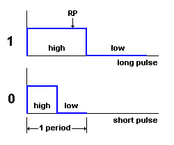
of a pulse is constant. MZ-700 uses a long pulse
to represent a bit containing a logical 1 and a short
pulse to represent a logical 0. To this refer to the monitor's routines
SHORT at location $0A01 and LONG at location $0A1A after downloading
the monitor's source code and the explanation below.
|
| Tape format |
|
The format of a file stored to tape is as follows:

The abbreviations used and their meanings are:
LGAP is a long GAP
SGAP is a short GAP
LTM is a long tapemark
STM is a short tapemark
HDR is the tapeheader
HDRC is a copy of the tapeheader
FILE is the file
FILEC is a copy of the file
CHKH is a 2 byte checksum of the tape header
or its copy
CHKF is a 2 byte checksum of the file or its
copy
L is 1 long pulse
256S contains 256 short pulses
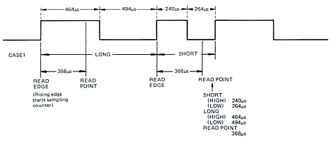
"LONG" is the data written for the bit value of "1"
and "SHORT" for the bit value of "0". Data is read
368µs after the rising edge of the data. The data is recorded
as a repetition of LONG and SHORT, with the same data block written
twice.
Data transfer with the cassette recorder is carried out on PC1, PC4,
and PC5 of the 8255. For more details to
this go to the next page now.
|
| Tape header and FILE creation |
|
The second block shown in the picture above containing the FILE
immediately follows the first block. The first block is written to tape
by the monitor's routine WRI at $0436 and the second block is written
to tape by WRD at $0475. WRI can be called too by the vector $0021,
WRD can be called too by the vector $0024. To this refer to my description
of the monitor's subprograms too.
|
| Format of the HDR, its copy HDRC and each byte
on tape |
|
The format of the tapeheader HDR is shown here.
Each byte of the header, the file, and the checksum
stored to tape is preceded by 1 long pulse in addition
to its 8 bits. The most significant bit is stored first then the least
significant bits are stored. To this see the monitor's source code at
$076A.
|
| Copies of HDR and FILE |
|
Both the header HDR and the file FILE are stored twice
on tape. These copies are labeld HDRC and FILEC in the
picture above. To this see WTAPE at location $048A.
|
| Logical bit presentation |
|
A bit of a byte is stored by a long pulse if the
bit contains a logical 1, otherwise it is stored by a short
pulse (PWM).
 |
|
 Each pulse starts logically with high ( mark ) generated by the
monitor program.
|
 The
values high, low, 1, and 0, or the rising edge, are logical definitions.
This means these values are processed by the monitor's program. The
physical values can be contrary to the logical values. The logical values
can be changed by the hardware connected to the output device 8255 on
the mainboard, by the hardware in the data recorder, and by the natural
magnetism used to store an information on tape. The
values high, low, 1, and 0, or the rising edge, are logical definitions.
This means these values are processed by the monitor's program. The
physical values can be contrary to the logical values. The logical values
can be changed by the hardware connected to the output device 8255 on
the mainboard, by the hardware in the data recorder, and by the natural
magnetism used to store an information on tape.
|
| Short and long pulses; timings |
|
The time period of each pulse consists of a various number of Z80 clock
cycles and depends on the number of instructions executed within the
monitor's program between two full pulses. The clock input of the Z80
in the MZ-700 is approx. 3.5 MHz and this means the duration time of
each clock cycle is: ( 3.5 x 10⁶ )-1 = 285.7 ns
( nano seconds ). Each time period of this square wave is a number of
clock cycles high ( mark ) and a number of clock cycles low ( space
). The duration times of high and low are almost similar. The duration
times of high and low are nearly a half of the duration time of one
time period.

( time values of the MZ-700 and, may be, also for the MZ-80K / MZ-80A
)
|
700/K/A
|
high ( mark ) µs |
low ( space ) µs |
total µs |
| long pulse |
464
|
494
|
958
|
| short pulse |
240
|
264
|
504
|
|
|
All values depending on the number of instructions executed
between two pulses.
The read point ( read edge ) is at 368µs.
|
| |
|
|
|
800
|
high ( mark ) µs |
low ( space ) µs |
total µs |
| long pulse |
470
|
494
|
964
|
| short pulse |
240
|
278
|
518
|
|
|
All values depending on the number of instructions executed
between two pulses.
The read point ( read edge ) is at 379µs.
|
| |
|
|
|
80B
|
high ( mark ) µs |
low ( space ) µs |
total µs |
| long pulse |
333
|
334
|
667
|
| short pulse |
166.75
|
166
|
332.75
|
|
|
All values depending on the number of instructions executed
between two pulses.
The read point ( read edge ) is at 255µs.
|
|
| GAPs |
|
There are two different GAPs: LGAP and SGAP. The GAPs
are used to synchronize the hardware and the software. The LGAP is a
long GAP containing 22,000 short pulses ( only
10,000 for the MZ-80B !! ) while the SGAP is a short GAP containing
11,000 short pulses. The LGAP appears at first
on tape in the block that contains the header HDR
while the SGAP appears between the header block and the file block.
LGAP takes nearly 9.614 seconds on tape ( 22,000 x 437µs ).
|
| Tapemarks |
|
Each GAP is followed by a tapemark.
The LTM signals a header block and the STM signals a file
block.
The long tapemark contains 40 long pulses followed by 40 short pulses
and 1 long pulse.
The short tapemark contains 20 long pulses followed by 20 short pulses
and 1 long pulse. All GAPs and tapemarks are written to tape by GAP
at location $077A.
|
| Checksums |
|
The checksum CHKH / CHKF contains the number of logical 1 bits.
CHKH in the header block contains this number of the header HDR
or its copy while CHKF in the file block contains this number
of the file FILE or its copy. If the checksum exceeds ( 216
)-1 ( greater than 65,535 decimal ) then the checksum shows the number
of logical 1 bits by modulo 216. CHK is stored into two bytes.
The most significant byte is stored first then the least significant
byte ( big Endian format ). This is done by the monitor's subroutine
CKSUM at location $071A.
|
| Reading data from tape |
|
The monitor subroutine RDI at loaction $0027 / $04D8 reads at first
the tape header and stores it to the RAM starting from location $10F0
and 128 bytes in length. Then the first copy is read by RDD at location
$002A / $04F8. If the first copy could be read without any error then
the load process stops otherwise the monitor tries to read the second
copy successfully.
The format of the MZ-tape shown above isn't used
consequently by the monitor program to read the tape. E.g. a GAP contains
up to 22,000 short pulses but the monitor reads and counts only the
first 100 pulses ( see the subroutine GAPCK at location $0FE2 ). The
remainig pulses are not counted but skipped.
A data bit is read from tape at the read point RP ( see last picture
above ). If the square wave is high at this time a logical 1 bit
is stored to the byte construct, otherwise a logical 0.
The readpoint time is at 368µs ( MZ-700 ) and starts at the rising
edge of a pulse logically going high.
If you want to know how to connect your data recorder to your PC and
then loading and saving your MZ-programs by DOS then click here.
|


