| MZ-700 memory map
( storage management )
|
|||||||||||||||||||||||||||||||||||||
|
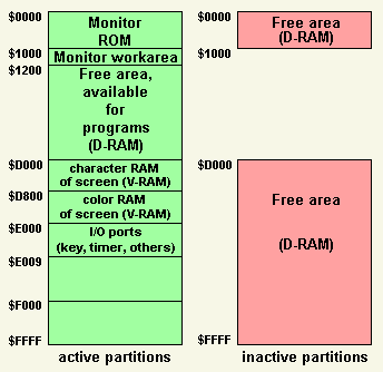
Storage structure at power on ( MZ-80K / MZ-80A mode )
|
|||||||||||||||||||||||||||||||||||||
|
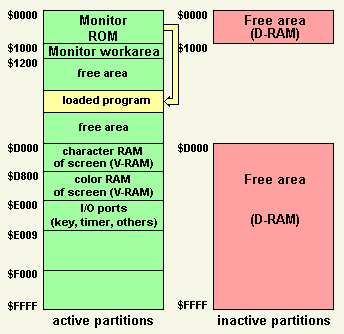
Storage structure after loading of a system program using the monitor's load command "L" ( bootstrap )
The execution starts at the storage address as defined by the tape header at location $16. The tape header is loaded into the monitor's work area starting at address $10F0 in the length of 128 bytes. The first byte at location $10F0, this equals to the tape header location $00, defines the attribute of the file. This will be the attribute for a program either written in assembler or written in BASIC, but it could be the attribute of a data file too. Special codes for MZ-80K files are also possible. The name of the file starts at location $10F1 in the length of 16 bytes and is followed by $0D ( CR ). If the name of the file is less than 16 characters in length, then the remaining bytes are filled with $0D. As described above the name of the file is followed by the order of the byte size ( 2 bytes ), the load address ( 2 bytes ) and the execution address ( 2 bytes ). A comment area in the length of 104 bytes starts at location $1108 and has no special meaning. Use this area for your own purposes.
You can find in the comment area of your original BASIC load tape a tiny program written in machine code to copy your BASIC tape. To get more details about this click here. |
|||||||||||||||||||||||||||||||||||||
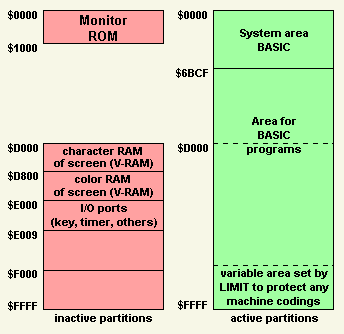
| Storage structure after
load of the BASIC interpreter ( MZ-700 mode, system initiation )
The BASIC interpreter will be loaded by the monitor into the storage starting at location $1200 as defined by the tape header. For this, no bank switching must be performed. To the area from location $1200 is RAM allocated every time. The execution starts at location $7D79 as defined by the tape header too. At startup the BASIC interpreter on tape has a trailer to load itself to the RAM location $0000. See the code: 7D79 AF XOR A
7D7A 110000 LD DE,$0000
7D7D CD3300 CALL $0033 ; perform time set (init to 0)
7D80 2A7111 LD HL,($1171) ; transfer displ. coordinates
; from monitor
7D83 225412 LD ($1254),HL ; to the BASIC interpreter
7D86 110000 LD DE,$0000 ; starting address
; for LDIR command
7D89 21796B LD HL,$6B79 ; length of data to be moved
; by LDIR
7D8C B7 OR A ; reset carry flag
; for arithmetic SBC
7D8D ED52 SBC HL,DE ; compute length
7D8F 4D LD C,L ; set BC to the start address
; for LDIR
7D90 44 LD B,H ;
7D91 210012 LD HL,$1200 ; set HL to start
; of data to be moved
7D94 D3E0 OUT (E0),A ; bank switch to RAM
; ($0000 - $0FFF)
7D96 EDB0 LDIR ; move data
7D98 C30000 JP $0000 ; execute BASIC
This program is available at the startup of the BASIC interpreter only, it will be deleted when the startup is completed.
You can switch the bank for accessing the I/O ports ( see memory mapped I/O ) by OUT ($E3),A and to return back by OUT ($E1),A ( see bank switching ) by imbedded machine code programs in your BASIC program ( BASIC command USR ). |
|||||||||||||||||||||||||||||||||||||
|
Storage structure at the time of manual reset
To this the monitor program in the ROM checks if the CTRL-key is pressed at startup.
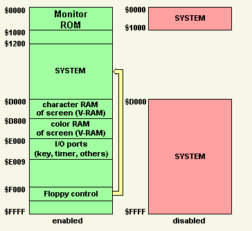
First, bank switching to the RAM at location $D000 will be done by the bank switching command OUT ($E1),A. Next, a tiny instruction set consisting of two instructions is stored to the top of the RAM in the length of 5 bytes starting at location $FFF0. Note, the RAM at this location is now active. Last, the instruction set at location $FFF0 will be executed. See the monitor's routine for this: CP $20 ; CTRL key? JR NZ,ST0 ; no, go normal process CMY0: OUT ($E1),A ; $D000 - $FFFF is RAM now ; and the ports and the V-RAM is deactivated LD DE,$FFF0 ; transfer address LD HL,MCP ; address of memory change program LD BC,$0005 ; byte size of memory change program LDIR ; move up memory change program JP $FFF0 ; start memory change program MCP: OUT ($E0),A ; $0000 - $0FFF is RAM ; and the monitor is deactivated JP $0000 ; start at $0000 in RAM ST0:.....normal process The first instruction of the set at the symbolic address MCP activates the RAM storage starting at location $0000 by the bank switching command OUT ($E0),A and by this, the monitor's ROM is deactivated. The second instruction is a jump command JMP $0000. If the CPU executed the jump command the execution of the program at address $0000 in the RAM starts. The same procedure as described above will be performed if you press the #-key first and then the CR-key at the monitor's response line and at any time you're working with the monitor. See the disassembled and reassembled monitor ROM ( download now ) at location $0057 for this procedure and take a look at the structure of the storage after execution of the procedure: 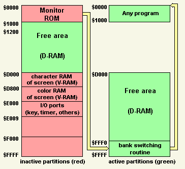
RAM between $0000 and $0FFF and between $D000 and $FFFF will be allocated by pressing the RESET key and the CTRL key coincidentally. |
|||||||||||||||||||||||||||||||||||||
|
Floppy bootstrap
|
|||||||||||||||||||||||||||||||||||||
| Bank switching
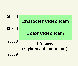
There are two areas which can be bank switched. The first area starts at location $0000 and ends at location $0FFF ( 4 kbytes ). The second area starts at location $D000 and ends at location $FFFF. You can allocate RAM or the monitor's ROM to the first area by bank switching commands. You can allocate RAM or the V-Ram and I/O ports to the second area by bank switching commands . The RAM you can allocate to both areas can be used by any programs. There is no limitation of the usage of the RAM. If you use a port address between $E0 and $E6 by the assembler command OUT (port#),A bank switching is invoked as shown in the following table.
For example OUT ($E4),A configures the storage like pressing the reset key does. The content of the accumulator register A is optional. You don't have to establish the register before executing the bank switch command. Any value of the register content is valid. OUT ($E0),A allocates RAM to the area between $0000 and $0FFF
and OUT ($E1),A allocates RAM to the storage between $D000 and $FFFF
whereas OUT ($E5),A prevents any access to the active storage between $D000 and $FFFF. The active storage between $0000 and $0FFF is accessible, but the active storage between $D000 and $FFFF is locked and un-accessible. For example, if you invoke bank switching to V-RAM by OUT ($E3),A or by OUT ($E4),A and you execute OUT ($E5),A next, any access to V-RAM and the I/O ports does not work properly. Otherwise, if you invoke bank switching to the RAM by OUT ($E1),A followed by OUT ($E5),A access to the RAM does not work properly. If you access the locked area by read, the data returned is invalid. If you access the locked area by write, no data will be written into the locked area. Any commands to access the locked area will be executed, but neither valid data will be read from the storage nor data will be written into the storage. You cannot bank switch the area between $D000 and $FFFF if a lock is active. No bank switching will be done if you try. You can unlock the area by OUT ($E6),A to get back access to the storage you had locked. Locking the RAM returns the RAM by unlocking and locking the V-RAM returns the V-Ram by unlocking. You can unlock the area by OUT ($E4),A too, but you get back the V-RAM and I/O ports even you had locked the RAM before. Using OUT ($E4),A is the same like resetting the MZ-700 manually or like turning the power on: The same structure of the storage will be built. The monitor ROM is activated too.
|
|||||||||||||||||||||||||||||||||||||
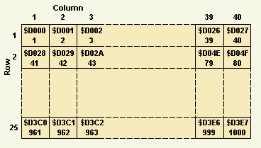
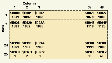
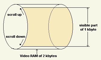
There are 2 Kbytes video RAM ( V-RAM ) available of the MZ-700, but 1 Kbytes is displayable only on the screen. The visible part of 1 Kbytes is scrollable within the available 2 Kbytes V-RAM.
This way of scrolling is available with the BASIC interpreter 1Z-013B, it is not available with the monitor 1Z-013A. The monitor program is not designed to use scrolling. The monitor scrolls up one line only showing the actual line in the last line of the visible part while the oldest line scrolls out at the top of the visible part. There is no way to show the line scrolled out again while the monitor is active. You can scroll down and up all of the available 2 Kbytes V-RAM with the BASIC interpreter. Pressing the keys SHIFT and cursor up coincidentally will scroll the V-RAM up and pressing the keys SHIFT and cursor down coincidentally will scroll the V-RAM down.
Click here to view the details about the V-RAM. |
