| 8253 sound functions
( Part I )
|
|||||||||||||||||||||||||||||||||||||||||||||||||||||||||||||||||||||||||||||||||||||||||||||||||||||||||||||||||||||
| General
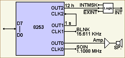
The control word at port $E007 of the counter #0 is set to mode 3 to operate this counter as a square wave generator for the sound generation. This takes effect by the value loaded into the control port $E007 during the setup of the 8253. The input signal SOIN of 1.1088 MHz is connected to the pin CLK0 of the counter and will be divided by a value loaded into the port $E004. The result is a frequency which will be outputted at pin OUT0. The output is the input to an audio amplifier. A loudspeaker ( 8 Ohm/1W ) is connected to this amplifier. The counter and its output can be started and stopped by port $E008.The following sections will show: how the sound generation by the monitor 1Z-013A is done,
|
|||||||||||||||||||||||||||||||||||||||||||||||||||||||||||||||||||||||||||||||||||||||||||||||||||||||||||||||||||||
| Ports of counter #0
This is an overview of the ports related to counter #0:
The following table shows all bits of the port $E008 and its functions. I put the table in detail here to complete the information about the 8253 ports but only bit D0 is important for this section ( start / stop counter #0 and tempo control ).
|
|||||||||||||||||||||||||||||||||||||||||||||||||||||||||||||||||||||||||||||||||||||||||||||||||||||||||||||||||||||
| Counter initiation
During monitor's startup the sound generator is set up and turned off by the following monitor instructions ( see the source code of the monitor ). The sound generator counter #0 must be turned off at startup, because the 8253 is in an undefined state after power on. This means, the counter may be in work and e.g. could output a tone to the loudspeaker if not turned off. See the setup of the counter #0 by the monitor during its startup: 0095 CDBE02 CALL MLDSP ;calls $02BE, melody stop 02BE 3E36 LD A,$36 ;counter control word 00110110 02C0 3207E0 LD (CONTF),A ;into port $E007 02C3 AF XOR A ;accu=0 02C4 3208E0 LD (SUNDG),A ;silence (bit D0=0 of port ;$E008 means stop counter #0) 02C7 C9 RET ;goback Please refer to the control word of the 8253. First $36 ( 00110110 binary ) is loaded by $02C0 into the control word
port. This means: Summary: The counter #0 is initiated to mode 3 to operate as a square wave generator, binary counting down and is to be read / load with the least significant byte first and the most significant byte last. This time the counter value isn't loaded. This will be done by a call of the melody play routine or by a call of the bell routine. I'll explain these routines in detail later. At last the counter will be stopped by $02C4 ( bit D0 of port $E008 set to 0 ). |
|||||||||||||||||||||||||||||||||||||||||||||||||||||||||||||||||||||||||||||||||||||||||||||||||||||||||||||||||||||
| Using the counter | |||||||||||||||||||||||||||||||||||||||||||||||||||||||||||||||||||||||||||||||||||||||||||||||||||||||||||||||||||||
| Outputting a tone by own routines
You can use the counter to generate any output frequencies within the following borders: The input to the counter is 1.1088MHz ( signal SOIN at pin CLK0 ). This means the max. output frequency at pin OUT0 will be 1.1088MHz too. For further details how to set the counter refer to the details of mode 3. The max. frequency will be invoked if you load $0001 into the
counter port $E004:
The min. frequency will be invoked if you load $FFFF ( 65,535
decimal ) into the counter port $E004: The counter starts if you set bit D0 of port $E008 and the counter stops if you reset bit D0 of port $E008. For example, to output a tone of approximate 10KHz load $006F into the port $E004. Compute the counter value as follows: 1.1088MHz / 10kHz = B000 116F00 LD DE,$006F ; load count register value B003 2104E0 LD HL,CONT0 ; address to port $E004 B006 73 LD (HL),E ; load least significant byte 1st B007 72 LD (HL),D ; load last significant byte last B008 3E01 LD A,1 ; set bit D0 B00A 3208E0 LD (SUNDG),A ; to start the counter output B00D ; at this point the loudspeaker outputs a tone of 10KHz To stop the output code this: B010 3E36 LD A,$36 ; mode set, ctrlword into B012 3207E0 LD (CONTF),A ; port $E007 B015 AF XOR A ; sets accu to 0 (all bits, D0 too) B016 3208E0 LD (SUNDG),A ; to stop the counter output ; reset bit D0 of port $E008 If your application uses the joystick(s) too, the port $E008 should be read into the register A by LD A,(SUNDG) and then use AND A,$FE to stop the counter. Using XOR A at location $B015 as shown resets all other bits of port $E008 too. |
|||||||||||||||||||||||||||||||||||||||||||||||||||||||||||||||||||||||||||||||||||||||||||||||||||||||||||||||||||||
| Outputting a tone by monitor subroutines
You can output a tone by your own routines using the ports as described above or by the following monitor routines:
Use MSTA to invoke the output and set RATIO at loc. $11A1 / $11A2 to the appropriate value before invoking MSTA. The valid range you can put into RATIO is from $0100 to $FFFF, this means that the frequency range goes from 4,331Hz to 16.9Hz.
For example to output a tone of 440Hz by MSTA set RATIO at location
$11A1 / $11A2 to $09D8 B000 21D809 LD HL,$09D8 ; Load count register value to invoke 440Hz B003 22A111 LD (RATIO),HL ; store value to RATIO at $11A1 B006 CD4400 CALL MSTA ; Start output by MSTA at $0044 B009 ; at this point the loudspeaker outputs a tone of 440Hz To stop the output invoke MSTP by a simple CALL only: B010 CD4700 CALL MSTP ; stop the output by MSTP at $0047
|
|||||||||||||||||||||||||||||||||||||||||||||||||||||||||||||||||||||||||||||||||||||||||||||||||||||||||||||||||||||
| Outputting a tone by the
bell subroutine
If the bell subroutine at loc. $003E is invoked a short tone of 880Hz comes over the loudspeaker ( note +A0 will be played ). To invoke the bell subroutine by your own program code only: B000 CD3E00 CALL BELL ; invoke bell at $003E The beep occurs only once per call. To get a beep everytime a key is pressed like the monitor command B does, code: B000 3A9D11 LD A,(SWRK) ;get beep status (on or off) B003 EE XOR $01 ;invert beep status/bit 0 B004 329D11 LD (SWRK),A ;store inverted bit 0 B007 C9 RET ;go back to caller If the routine shown above is invoked again the bell output stops until
the routine is invoked again |
|||||||||||||||||||||||||||||||||||||||||||||||||||||||||||||||||||||||||||||||||||||||||||||||||||||||||||||||||||||
| Playing specified melodies
You can use the counter to play melodies by using the following monitor routines:
Before invoking MELDY you have to set the tempo of the melody, you have to define the notes, their time periods and their octaves, and the rests and their time periods, and . Read the following sections which will show you how to do this. A note has its own pitch ( its frequency ). An octave is a musical definition of a set of 7 notes, each octave having its own frequency range. The time period of a note is the time of a "note's life". The rest is a pause between two notes ( last and next note ) and the time period of a rest is the time of a "rest's life". The tempo is the tempo of the whole melody played. |
|||||||||||||||||||||||||||||||||||||||||||||||||||||||||||||||||||||||||||||||||||||||||||||||||||||||||||||||||||||
| Setting the tempo of a
melody
The tempo will be set by XTEMP. Set the accumulator register A to any value of the valid range from $01 to $07. The meaning of the values is as follows: slow: $01 ( Lento, Adagio ) If you don't use XTEMP to set the tempo before invoking MELDY the default value $04 ( moderato / middle ) is used. For example, to set the tempo to $07 code the following instructions: B000 3E07 LD A,$07 ; load tempo $07 B002 CD4100 CALL XTEMP ; execute tempo set routine ; at location $0041
B000 3E07 LD A,$07 ; load tempo $07 B002 329E11 LD (TEMPW),A ; into $119E |
|||||||||||||||||||||||||||||||||||||||||||||||||||||||||||||||||||||||||||||||||||||||||||||||||||||||||||||||||||||
| Defining notes and rests
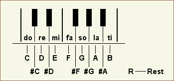
Before you call MELDY you have to define a character string containing your notes, rests, etc. and the register DE must point to the address of this character string. The character string is to be defined like the definitions of the BASIC command MUSIC and must be terminated by $0D or $C8. On return to the caller the carry flag is set to 0 normally. If the execution of the melody subroutine is terminated by a user BREAK ( SHIFT- / BREAK-keys ) then the carry flag is set to 1 on return to the caller. Valid notes are C, D, E, F, G, A,
B, and additional, a preceding # to play a seminote is
valid, for example, #C, #D, 
|
|||||||||||||||||||||||||||||||||||||||||||||||||||||||||||||||||||||||||||||||||||||||||||||||||||||||||||||||||||||
| Defining time periods
A numeric suffix from 0 to 9 is valid and specifies the time period of the note / rest to be played. See the following picture for all valid time periods: 
The tempo control part3 is used to wait a computed number of cycles before stopping the note / rest. The number of cycles a note / rest will be played depends on the time period value shown above. The tempo a melody is to play set by XTEMP or set by TEMP directly ( see above ). Further details about the computation etc. follow now. The tempo control part3 is an oscillator and his output is available if bit D0 of the port $E008 is read. The cycles of this oscillator were counted to compute the time period a note / rest is to play. I assume that the engeneers of the MZ-hardware designed the time period 9 of a whole note / rest to 1s if the tempo is set by XTEMP to $01 ( slow ). This means that the time for a 1/32 note / rest is 1/32 second if the defined time period is 0 ( see the figure above ). Looking at the schematic diagram of the tempo controller oscillator ( part3 ) to calculate the nominal time period does not help because the capacity C86 with 1µF can have a big tolerance which rather influences the output frequency. Calculating the frequency by the electronical parts as designed by an engeneer ( R110, R112, and C86 ) and by the following formula for the timer chip 556 ( astable multivibrator ) results to 38.1Hz: 1.44 / ((R112 + 2 x R110) / C86) Insert R in Ohms, C in Farad: R112=1.8K, R110=18K, C86=1µF 1.44 / ((1.8 x 10³ + 2 x 18 x 103) / 1 x 10⁻⁶) = 38.095Hz
The following table shows all possible, resulting number of cycles and values of time periods. The values enclosed in paranthesis base on 32Hz ( 31.25ms/cycle ) assumed as the correct output frequency of the timer oscillator and they show the timing in ms ( milliseconds ). The cycles are shown in bold digits.
The values are computed by a table in the monitor called OPTBL located at $029C, the defined time period, and the defined tempo. The number of cycles is computed by: #cycles = table value of the time period TP x tempo value The table values are:
For example: If you code R9 and a tempo of $04 then a silence rest between two notes of 32 x 4 = 128 cycles will occur. If the frequency of the oscillator is 32Hz then the time of the silence rest between the two notes will be: t(s) = 1 / frequency(Hz) x # of cycles More details about this when I explain the related monitor subroutines ONPU and RYTHM. |
|||||||||||||||||||||||||||||||||||||||||||||||||||||||||||||||||||||||||||||||||||||||||||||||||||||||||||||||||||||
| Defining an octave
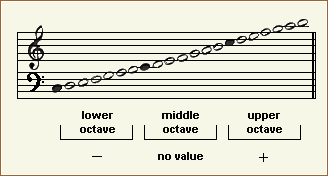
A preceding - or + specifies the octave. Code - for the lower octave and + for the upper octave. Nothing specified plays the standard / medium octave. $CF specifies the lower octave too. $D7 specifies the upper octave too. 
|
|||||||||||||||||||||||||||||||||||||||||||||||||||||||||||||||||||||||||||||||||||||||||||||||||||||||||||||||||||||
| Example
Try the following example: B000 1150B0 LD DE,$B050 ;address to string to be played B003 F7 RST 6 ;execute melody play at $0030 B004 C3AD00 JP $00AD ;return to monitor and set the area starting from $B050 to the following values by the "M"-command: B050 2B 41 33 2B 23 46 31 2B +A3+#F1+ B058 41 2B 42 33 41 2B 44 2B A+B3A+D+ B060 23 46 31 41 2B 44 33 41 #F1A+D3A B068 2B 44 2B 23 46 31 41 2B +D+#F1A+ B070 44 33 2B 23 46 31 41 2B D3+#F1A+ B078 44 2B 45 2B 23 46 2B 47 D+E+#F+G B080 2B 41 33 52 0D +A3R. Now execute the jump command JB000 and Beethoven's sonate D-dur ( opus 25 ) should be played as shown in the following picture. You can set the tempo as described above. 
|
|||||||||||||||||||||||||||||||||||||||||||||||||||||||||||||||||||||||||||||||||||||||||||||||||||||||||||||||||||||
| Setting the volume
The volume can be controlled only manually by the volume control ( potentiometer ) at the reverse side of the MZ-700. Do you need additional information or details to the related monitor subroutines? If so, click here. |
|||||||||||||||||||||||||||||||||||||||||||||||||||||||||||||||||||||||||||||||||||||||||||||||||||||||||||||||||||||
