|
As explained in the
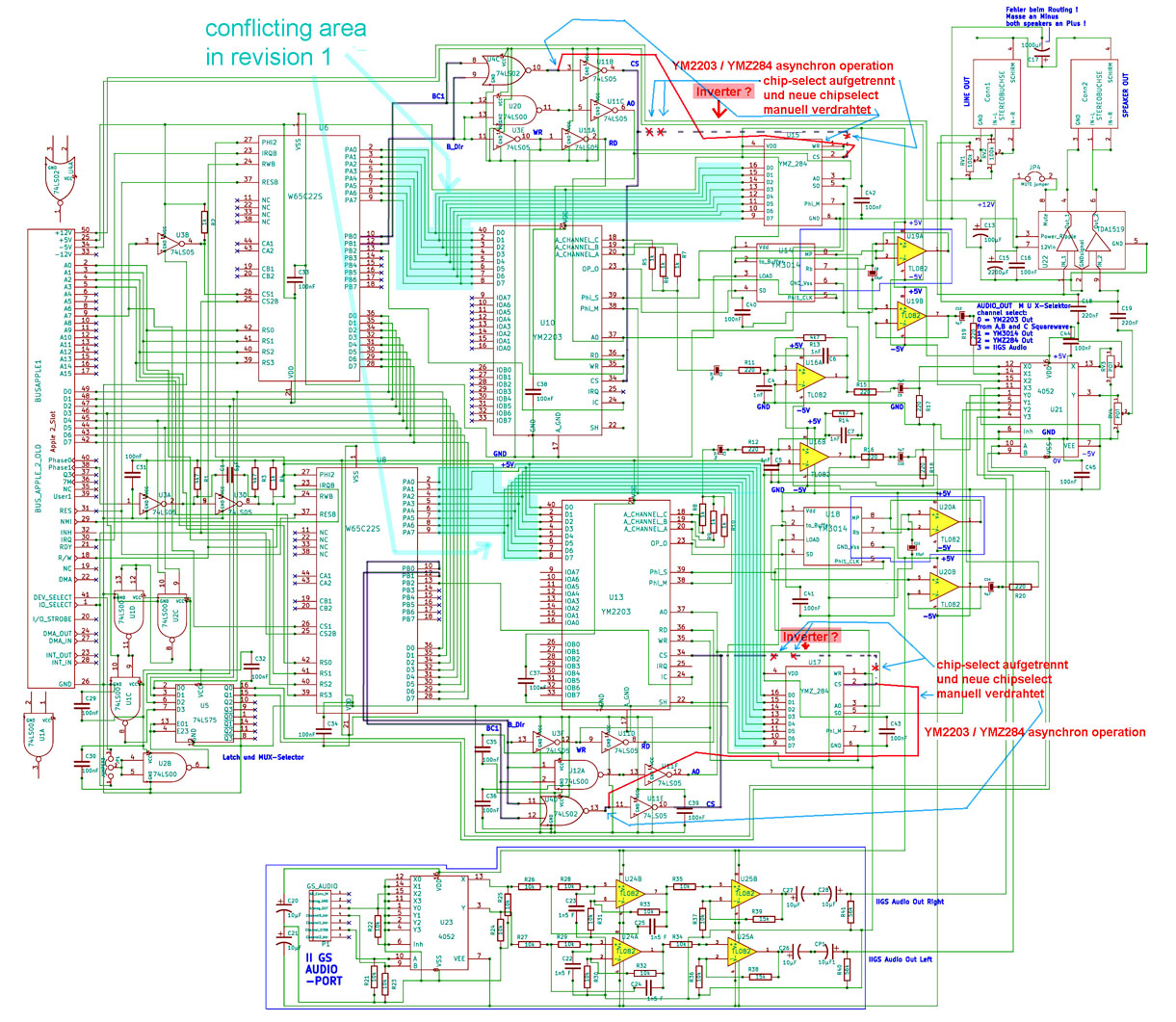
previous page the first revision of the card has occasionaly
problems with the handling of the databus between the
WD65C22 and the
soundchips YM-2203 and YMZ-284. This problem is solved in the second
revision. See the circuitplan of the second revison below
and put your attention to
the CS-lines ( CS=Chip Select ) and the driving of that lines in the
circuitplan below:
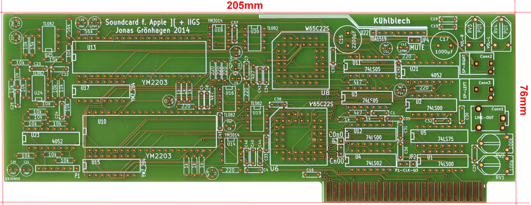
At the second revision also the area of
components related to the IIGS soundport was set apart from the
audiopart related to the audio-preamps of the
soundchips and it turned out if another kind of coolingsink would be
used at the poweramp chip the space can be optimized and it also turned
out to be
better, if at least the connectors for the speakers could be set
inwards at the card giving more space between connector and rearplate of
the IIGS for
rectangled plugs.
The new layout of the card resulted to this design:
and the completed card looks like this:
| |
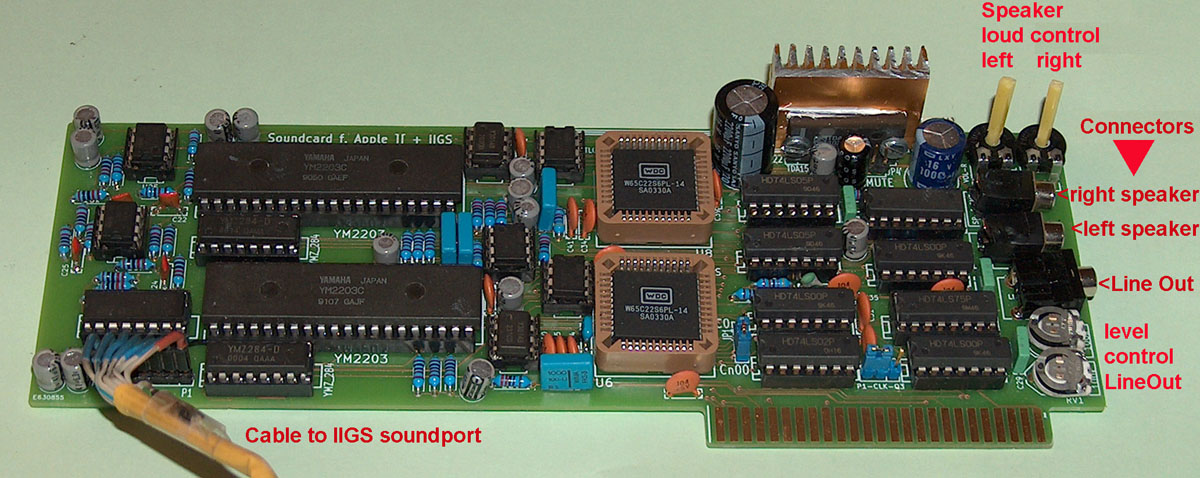 |
|
But even this second version can´t be the
final solution, because it does not unleash the total abilities of the
card. Up to the moment it only supports
4 abilities:
1. emulating the Mockingboard A
2. using the additional modes of the YMZ-284 ad its DA
capabilities
3. using the additional modes of the serial DA of the YM-3014
4. amplifying the sound taken from the IIGS soundport
But the "ideal" solution would be the ability to "add" or "mix" any of
this 4 sources in any combination.
This would give the contol of a very advanced soundsystem to the user
with at least a dozend of different soundsources per channel:
rectangular wave generators,
sinewave generators and
noise generators
and not to forget the ability to use also the FM-abilities.
But such a "final revision" would demand major
changes to the previous designs:
A) the "switching modes" must be expanded to 8 or 16
switchmodes per channel
and they must get
syncronized with the related Chipselect lines of the selected
devices -
that demands change from
4052 analog switches ( 2 x 4 in to 1 out ) to 4051 analog switch ( 1 x 8
In to 1 out )
B) the databuses must get latched so that after one
source has been set and programmed it must keep this setting till it is
released while during
"hold-time" the next
sources might be set by their latches..... and that latches must be
syncronized with the related databus latches.
C) not a demand but a wish, would be the ability to set
the amplitude ( loudness ) by digital potentionmeter and software
instead of using hardware
trimmers in such a
case its probably a good idea for saving additional space by not keeping
the connectors to the peripherial speakers and LineOut
"on the board" -
but instead using a row of pinconnectors and using an external aluminium
"connector-plate" that can be mounted to the rear plate
of the Apple.
and there is only limited amount of additional space availiable to the
card - in "worst case" this might require the use of a PAL aiming to
reduce the amount
of logic chips at the board.
The next level of revision is at the
next page:
|