|
While building up a replication of
the Apple-1 the user might face a problem:
when the board is powered up and all solderingjoints look perfect
by inspection and powerlines show the defined voltages and a
inspection of the timingsignals with an oscilloscope show the
correct rectangle wave the system srill might refude to boot correct
to the prompt.
In such a case it´s not allways usefull to inspect the total system
with a oscilloscope - due to the fact that the sxpected signals might be
viewable but not working in the correct condition.... In such a
case it is more usefull to make a diagnosticcard and bringup the display
of
all signals availiable at the system.... this will enable to
detect if a adressingline or adataline is hooked up at a specific adress
while bootup
is performed or if for example a controling line like thge reset or
NMI is blocking the startup of the system....
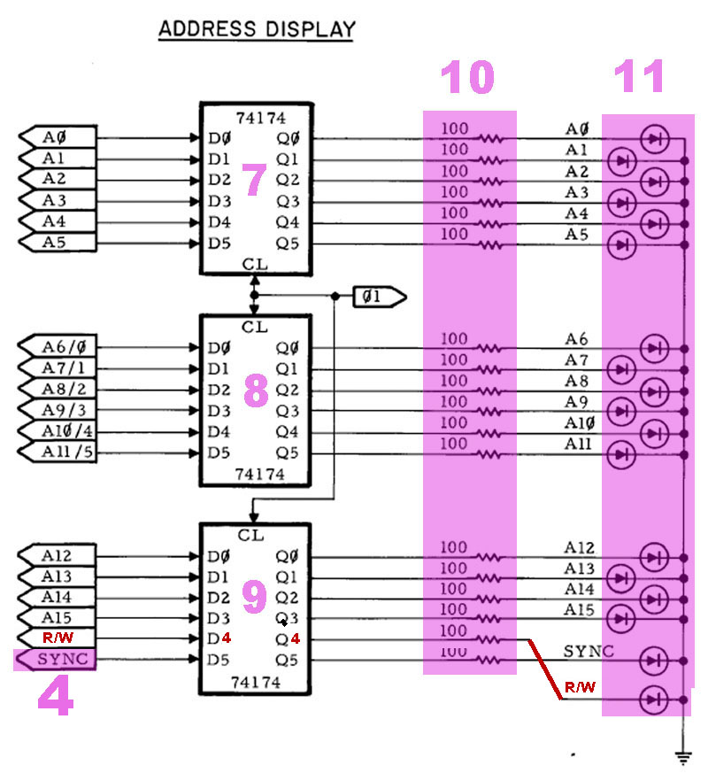
Within the Apple-1 manual there is at page 12 a circuitplan
proposed as "adressingdisplay". But this plan only brings up the display
of
the adressinglines and the datalines as well as the controllines
and clockinglines can´t be view with that proposal. At the other hand at
the same pageof the Apple-1 manual there is also a proposal how to
make a stepping logic for single steps or cycles at the system...
this proposal is quite interesting for debugging programms ..... At
the other hand that page does not make nay proposal about a "reset"-
button or any kind of use of the NMI-line.
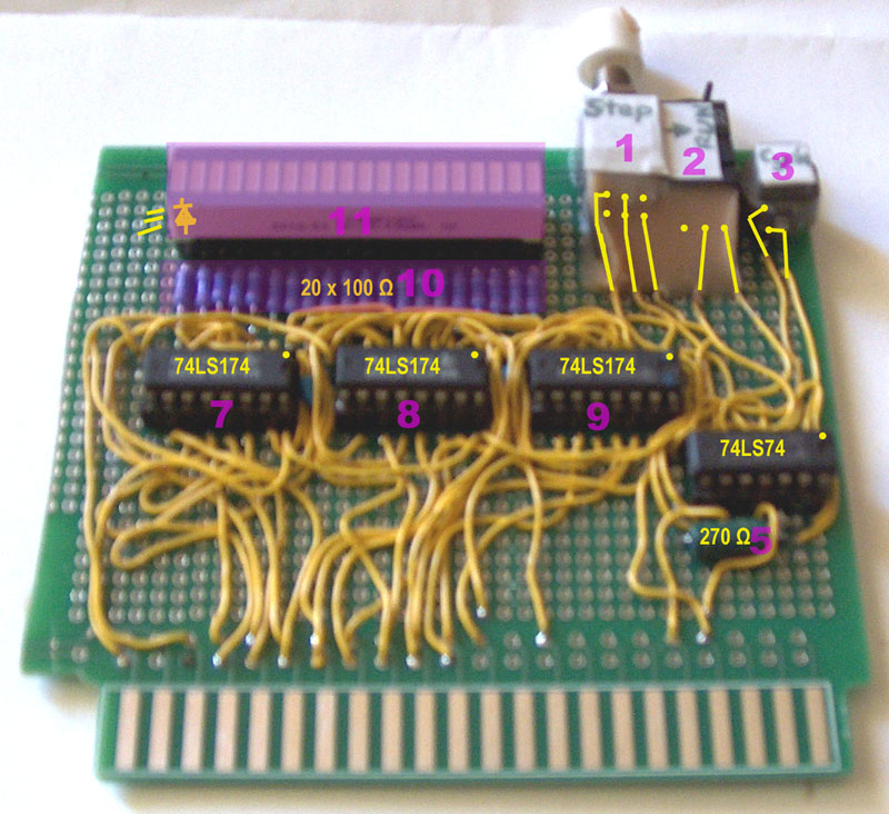
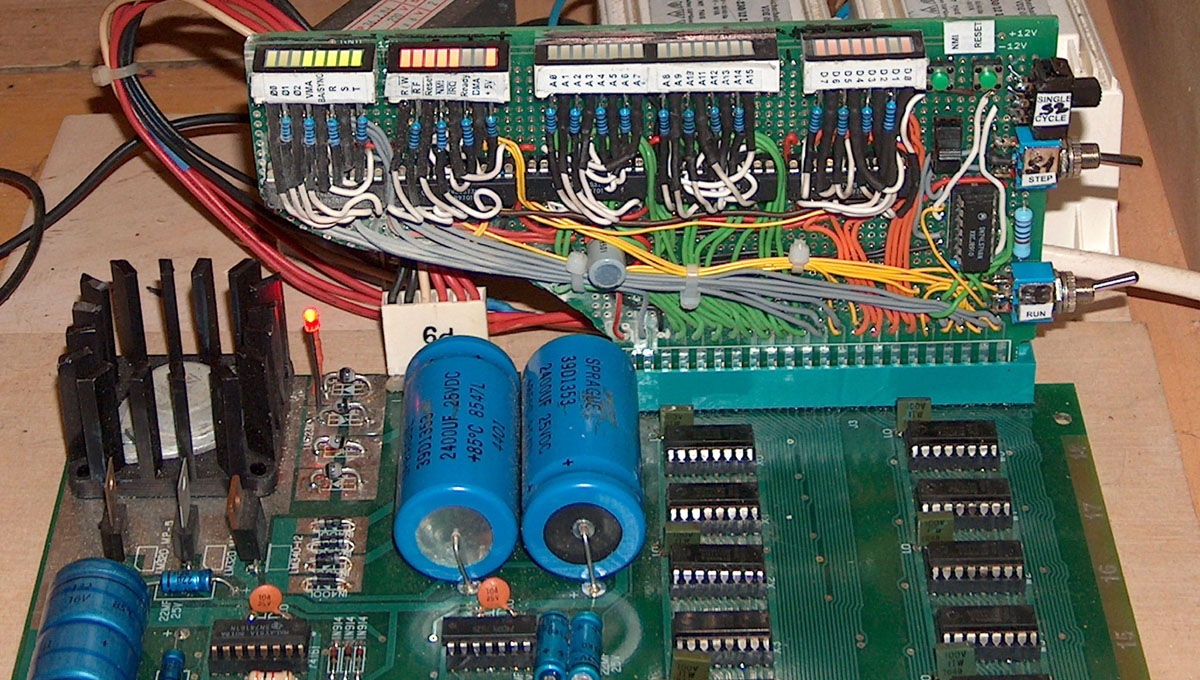
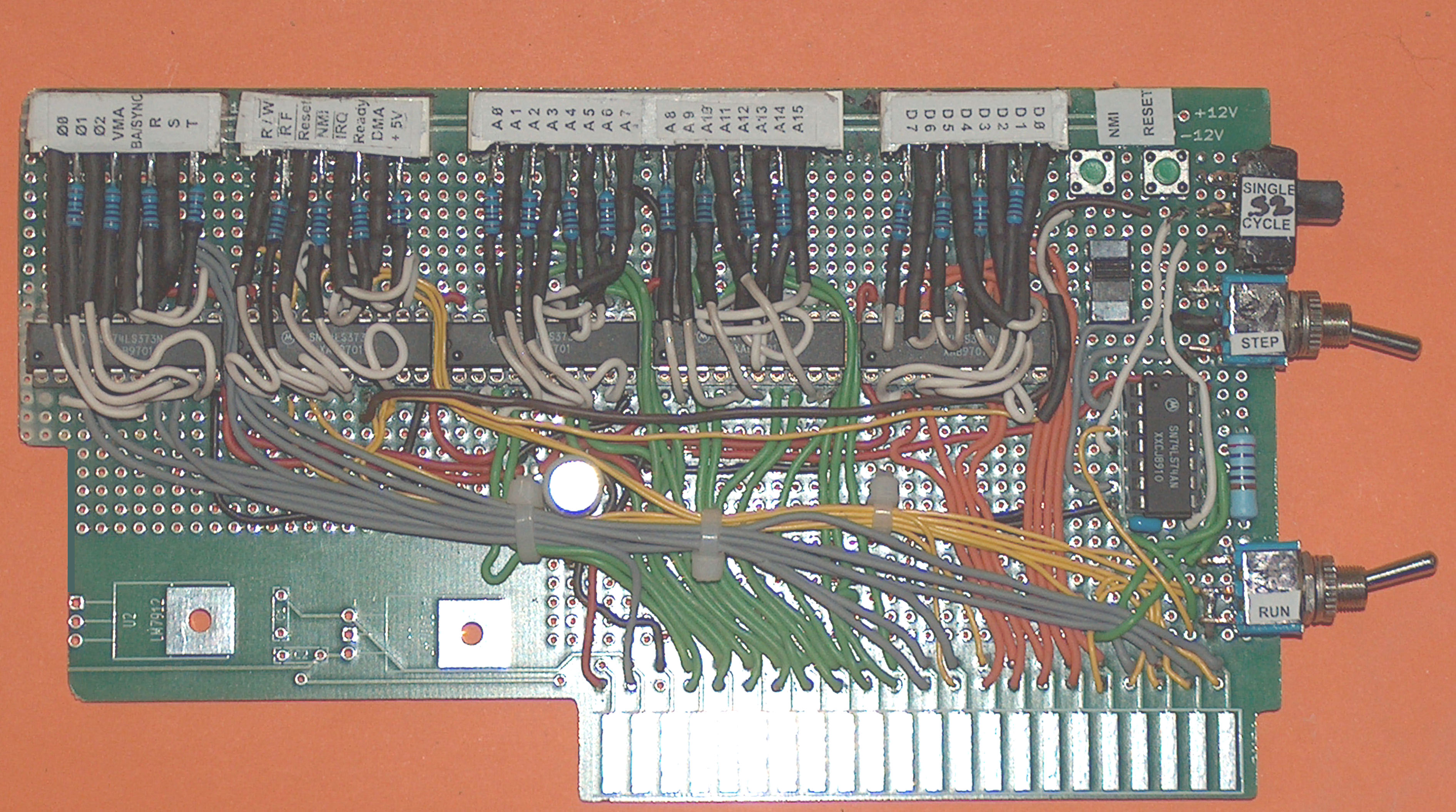
I have therefor made a card with a combination to display all
signals availiable at the slot : adressinglines, datalines, controllines
and
clockinglines as well as the so called selectionlines R, S and T
which will be used for selecting expansioncards and generated by the
74154 at the center of the replicationboards and responsible for
the hardcoded adressing of the adressing space of the replication as
well as also containing the stepping logic for debugging and
offering a resetbutton and a button to access also the NMI-line.
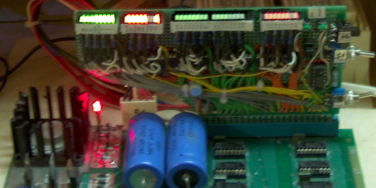
Another aspect of the card is that like in the original proposal
the card shall "latch" the display. This is by explenation "a kind of
static
picture" of the conditions at the signalbus. But for degugging
process it´s more usefull to view in general the "dynamic" process at
the
signalbus. Therefor the card contains a switch
(S6) that permits to decide in which kind of "mode" the display
shall operate. That permits the
user to decide if he wants to track the dynamic operation of the
system and accepting that some signals are that fast that a user can´t
watch the fast transitions of the signals but recognize the
operation or if the user want´s to take a single "timeshot" of the
conditions.... To tell
the truth - it´s mnot completely "invisible" if transitions are
performed at the signallines.... in fact if fast transitions occur at
the
signallines it just looks like the LEDs get "dimmed" while static
lines without change will remain at full brightness of light if siganl
is
at "high" state or total darkness if the signal stays at "low"
state.
Due to the fact that at the expansionbus there are 44 connections -
of only 5 lines contain power and the remaining 39 lines are related
to signals it is recommended to use the 74373 as "latch" instead of
the 74174. the 74174 only latches 6 lines ( resulting to the need of
7 ICs for the 39 signals ) while the 74373 latches 8 lines and only
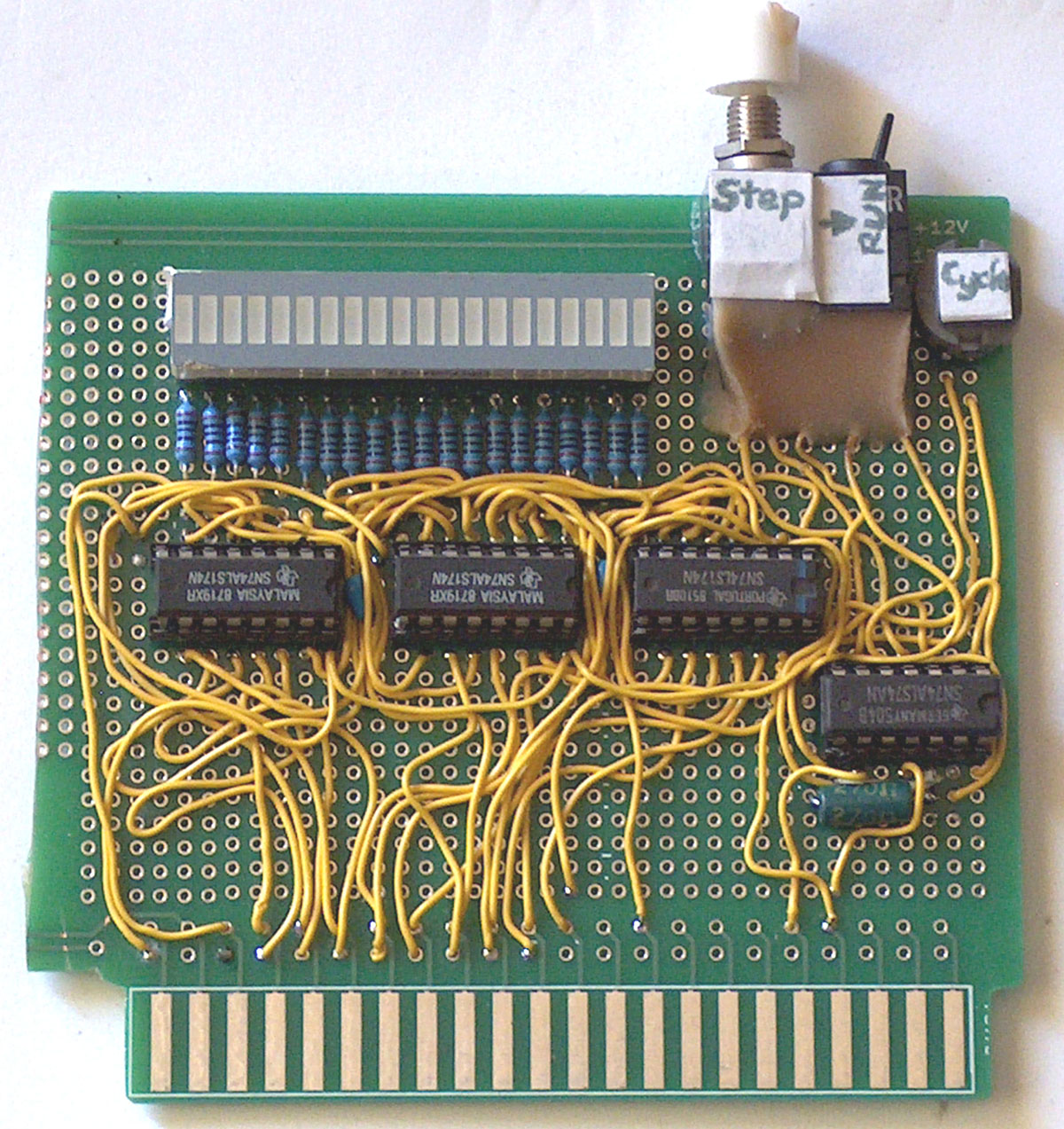
5 ICs will be requested. Another aspect will be the use of power....
using normal single LED with each requesting 20 mA for emmiting
light would make summary of 780 mA not adding the internal use
of the ICs .... it´s therefor recommended to use instead so called
LED-bars .... that LED often only request 12 mA for full lighting up and
therefor will drop the demands to the powersuply from 780 mA down
to 468 mA cutting the requested use of power by 40%.
|