The switch is located adjacent
to the power connectors.
Pictured in the rear position (towards rear of computer).
to the power connectors.
Pictured in the rear position (towards rear of computer).
| Home |
Card/s Fitted |
Required SW1 Setting |
Comment |
|---|---|---|
MDA only |
Rear position |
If in the wrong position, "501-CRT Error" will be seen on screen at power-on. |
CGA only |
Front position |
If in the wrong position, "401-CRT Error" will be seen on screen at power-on. |
EGA only |
Either position |
|
MDA + CGA |
Rear: MDA is to be the primary of the two Front: CGA is to be the primary of the two |
Info source: Page 3-26 of IBM document here |
|
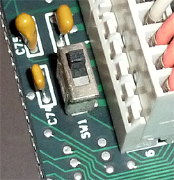
The switch is located adjacent to the power connectors. Pictured in the rear position (towards rear of computer). |
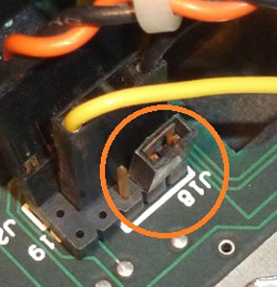 |
The jumper is located at the front of the motherboard. Pictured in the '512 KB' position. |