| Home |
| Switch 1: | ON : Normal setting OFF: Continously perform the Power On Self Test (POST) |
| Switch 2: | ON : 8087 math coprocessor chip is installed ( IC socket U4, adjacent to power connectors) OFF: 8087 math coprocessor chip is not installed |
| Switches 3 and 4: | Installed motherboard RAM. 3=ON , 4=ON: Only bank 0 populated 3=OFF, 4=ON : Only banks 0/1 populated 3=ON , 4=OFF: Only banks 0/1/2 populated 3=OFF, 4=OFF: Banks 0/1/2/3 populated |
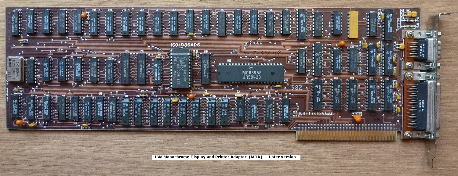
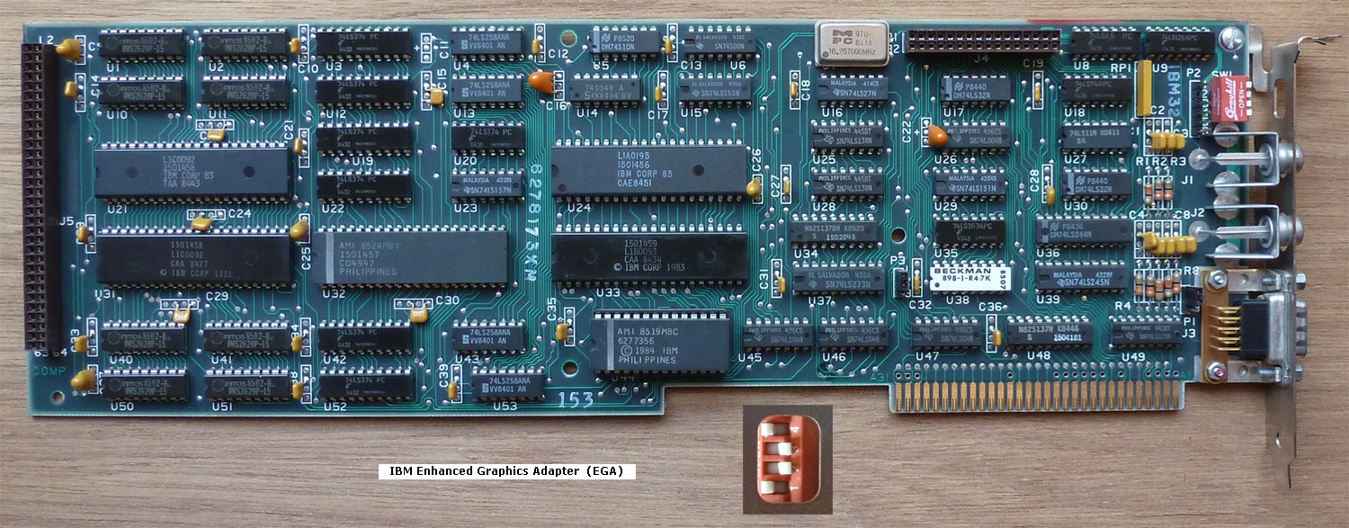
| Switches 5 and 6: | Video card type. 5=OFF, 6=OFF: MDA (monochrome) 5=OFF, 6=ON : CGA, at 40 column by 25 line mode 5=ON , 6=OFF: CGA, at 80 column by 25 line mode 5=ON , 6=ON: Cards with a BIOS expansion ROM (e.g. EGA / PGA / VGA) |
| Switches 7 and 8: | Floppy drive count. 7=ON , 8=ON: 1 floppy drive 7=OFF, 8=ON : 2 floppy drives 7=ON , 8=OFF: 3 floppy drives 7=OFF, 8=OFF: 4 floppy drives |