

MZ-80K Hints and Tips |
|
This section ranges from a simple idea to give better access to the
tape heads, through external security, all the way up to memory expansion.
|
| Hardware modifications to the MZ-80K |
| How to get at the tape heads ( using
normal sized fingers ) |
For improved access to the tape heads, for cleaning etc., press the button
to open the cassette lid, then carefully, push inwards the two plastic
lugs that stop the lid opening further. Once these are clear of casing,
the lit will open a lot further.
|
| How to fit a "RESET" switch
|
|
Some computers - but not the MZ-80K have a RESET switch which is useful
when a program "hangs up". Without such a switch the only
solution is to turn off the power, so here is the alternative.
- Switch the computer off, and disconnect from the mains supply.
- Carefully turn the computer upside down, and remove the four screws
that secure the bottom plate.
- Turn the computer the right way up, and lift the top. ( Keyboard,
picture tube, and cassette ).
- Lock the support hinge and locate the RESET switch terminals, that
look like this:
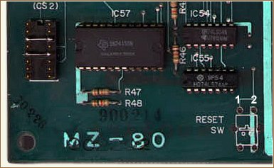
I've inserted numbers 1 and 2. They originally do not exist on the
PCB.
- Solder, or otherwise properly connect, a pair of wires to terminals
1 and 2.
- Bring these wires out to the side or back of the computer, where
you can drill a hole and fit a suitable switch.
- The switch can be of any type, ( e.g. push-button ), that will temporarily
connect the two wires together.
Having fitted this switch, you can take several actions after pressing
it:
- Type GOTO$1200 for a fresh start with BASIC, ( Program lost ).
- Type GOTO$1260 for a "WARMSTART". ( Program retained ).
- Type GOTO$1050 to SAVE, or GOTO$1060 to VERIFY a machine code copy
program.
- Type GOTO$2000 ( usually ! ) to restart a machine code program.
 This
switch can be used to BREAK out of machine code programs, but it will
not help in certain other situations, ( if you have been experimenting
with certain POKEs or USRs for instance ). This
switch can be used to BREAK out of machine code programs, but it will
not help in certain other situations, ( if you have been experimenting
with certain POKEs or USRs for instance ).
|
| Connecting to a domestic TV |
|
This can be a very useful facility, enabling your video picture to be
shown on one or more remote TV screens around a room, ( especially useful
for teachers ).
This should NOT be attempted, however, by anyone with no electronics
/ electrical knowledge, as only the basic principles are dealt with,
as follows:
- What you need, basically, is a simple UHF modulator, of the type
used in TV games. This is available quite cheaply from most electronics
or TV component stockists.
The output from this can be taken to one or more coaxial sockets,
mounted on your MZ-80K casing, and can be "tuned into",
( probably around channel 36 ) by one or more domestic TVs.
- This kind of modulator requires two inputs; a power supply, and
the picture signal.
- The power supply, usually 6 - 9V DC, may be taken off the MZ-80K
12V supply, using a "dropping" resistor to reduce the voltage,
( probably a few hundred ohms ), and a Zener diode to regulate it.
- The picture signals are taken off the five-pin connector CN2, on
the printed circuit board inside the MZ-80K. You need two connections:
One to pin 2 for the video sync pulses, and one to pin 3 for the video
signals. ( Pin 1 is clearly marked on the PCB ).
- If both these are taken off via two preset resistors, ( of a few
K ohms ), then their levels can be adjusted for a good picture.
- These signals are then combined, and fed into the video input of
the modulator via a small current-limiting resistor, and a larger,
( multi-K ohm ) resistor to Ground.
- If you don't understand most of this, then don't do it! ( Use mirrors
instead ;-)
|
| Fitting extra memory to your MZ-80K |
|
If you have a 20K, 24K, or 26K machine you can upgrade its memory size
to a maximum of 48K by adding and / or changing the dynamic RAM chips
and making a few extra socket connections. This should not be attempted,
however, unless you have the appropriate knowledge or experience.
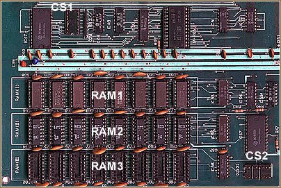
The RAM chips ( types 4116 and 4027 ) are located in three lines of
RAM sockets labeled RAM1 - RAM 3. Their configurations are governed
by the connections made on the two small connector sockets CS1 and CS2
which have 16 connector pins ( 8 on each side ) numbered 1 - 8 and 9
- 16.
You can upgrade to any size by adopting one of the arrangements shown
below.
For example, to upgrade a 24K machine to 36K you need to change the
4K of RAM in the bank RAM2 for 16K ( 4116 ) and change / add the pin
connectors on CS1 and CS2 as shown.
| Machine |
RAM arrangement |
Pins to connect |
| 20K |
RAM bank 1 - 16K ( 4116 ) |
CS1 - 8 to 9
CS2 - 3 to 14, 5 to 12 |
| RAM bank 2 - 4K ( 4027 ) |
| RAM bank 3 - none |
| 24K |
RAM bank 1 - 16K ( 4116 ) |
CS1 - 4 to 10,
8 to 9
CS2 - 3 to 14, 5 to 12 |
| RAM bank 2 - 4K ( 4027 ) |
| RAM bank 3 - 4K ( 4027 ) |
| 36K |
RAM bank 1 - 16K ( 4116 ) |
CS1 - 4 to 13,
5 to 12, 6 to 11, 7 to 10, 8 to 9
CS2 - 2 to 15, 3 to 14, 5 to 11 |
| RAM bank 2 - 16K ( 4116 ) |
| RAM bank 3 - 4K ( 4027 ) |
| 48K |
RAM bank 1 - 16K ( 4116 ) |
CS1 - make all
connections, straight across
( e.g. 4 to 13 )
CS2 - 1 to 16, 2 to 15, 3 to 13, 5 to 11 |
| RAM bank 2 - 16K ( 4116 ) |
| RAM bank 3 - 16K ( 4116 ) |
|
| A monitor of your own |
|
The present Sharp monitor is held in a 2332 chip which can easily be
changed to a 2732 by connecting pin 18 of the socket to GND, taking
the track which is connected to pin 18 and connecting it instead to
pin 21 and cut the existing track from pin 21. To alter the existing
monitor, all you have to do is to use an Eprommer to copy the monitor
to RAM, alter it to suit yourself, and then program it into a 2732 to
put in the socket.
Alternatively you can use a 2532 EPROM. Using this type of EPROM you
can exchange the monitor ROM by this chip without any hardware modifications.
|