Sharp logo
The Power Supply Unit 
( of the MZ-700 )  

The Power Supply Unit of the MZ-700
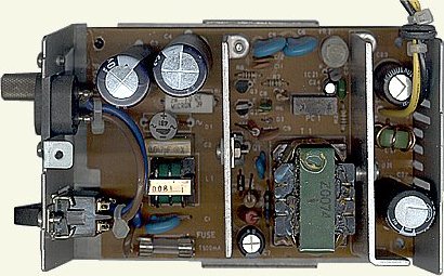
( point to an element to read by the tooltips its data )


The Power supply supplies all components of the MZ-700 with 5V DC / 3.75A.


Power supply circuit description


( see the schematic diagram )

  1. AC source power is rectified through the diode bridge ( RB-156 ).
  2. Current flowing through the primary coil of T1 is switched by means of Q1 so as to induce electromotive force in the secondary coil. To protect voltage fluctuation on the primary side, Q2 is implemented, which will become active to deactivate Q1 by dropping the base of Q1 to GND when voltage increase occurs on Q2.
  3. The electomotive force induced in the secondary coil is rectified through D21, and DC 5V is derived from the network consisting of C22, C23, and L21.
  4. For circuit stabilization against load fluctuation, we use IC21 ( shunt regulator ), PC1 ( photocoupler ), and Q3 ( transistor ). When the gate of IC21 is above 2.5V after sensing the 5V output by means of R22, VR21, and R23, it makes IC21 active and then PC1 active.
    As the base voltage of Q3 increases with activation of PC1 photo-transistor, it makes Q3 active and drops the base of Q1 to GN so as to turn off Q1.
    Although it is possible to adjust the DC 5V voltage by means of VR21, it needs to put the CPU PWB into connection.

Block diagram of the MZ-700 Power Supply


TROUBLESHOOTING

1. Trouble kind
Because different location has to be repaired depending on a kind of trouble, you have to check, the output voltage in the first place. ( Apply source voltage of 220 to 240V with a 3.75A load connected to the output. )

  1. No output ( 0V )
  2. Low output ( 1 to 4V )
  3. High output ( 7 to 10V )
  4. Abnormal increase of output ripple ( several hundreds millvolt )

2. Finding where is in trouble
2-1. In the case of "No output ( 0V )"

Case: No output (0V )
(*1): If the output voltage were to be still 0V without blowing the fuse after replacement of Q1, proceed to steps decsribed to the left of the troubleshooting flowchart.

2-2. When extremely low output voltage is encountered

Case: Extremely low output voltage

2-3. When extremely high voltage is encountered ( 7 ~ 10V )

Case: extremely high voltage

2-4. Abnormal increase of output ripple

In case irregular increase is seen for the output ripple like the one below, it needs to replace C22 and C23 with new ones because they have been fatigued.

Case: abnormal increase of output ripple

Read and download data sheets ( ICs, transistors, diodes etc. )

View the schematic diagram

Read the technical data

Read a funny article about "Repairing Power Supply Units"

Close window

Go to the top of this page Home

last updated September 23, 2002
sharpmz@sharpmz.org

Diode Bridge D1 ( RB156 ) Transformer T1 ( Z0074 ) Q3 Transistor 2SC1213D Q2 Transistor 2SC1213D Q1 Transistor 2SC3150 R5 Resistor 1.0Ohm 1W +/- 5% R3 Resistor 220KOhm 1W +/- 5% IC21 ( shunt regulator ) TL0431C PC1  ( photocoupler ) PC-511 VR21 1KOhm ( DC 5V adjust ) D21 Diode C82-004 D3 Diode 1S2076A L21 Filter coil Z0075 R1 Resistor 10Ohm / 2W */-10% R7 Resistor 150Ohm 0.25W +/- 5% R9 Resistor 3.3KOhm ( 2.7~3.9 ) 0.25W +/- 5% R6 Resistor 150Ohm 0.25W +/- 5% R21 Resistor 100Ohm 0.25W +/- 5% C11 Capacitor 0.1µF; C12 Capacitor 6.8nF C25 Capacitor 333pF 500V C22 Capacitor 4,700µF 10V C23 Capacitor 1,000µF 10V F1 Fuse T500mA